Book of shooting toys patent drawings
•
6 gostaram•6,356 visualizações

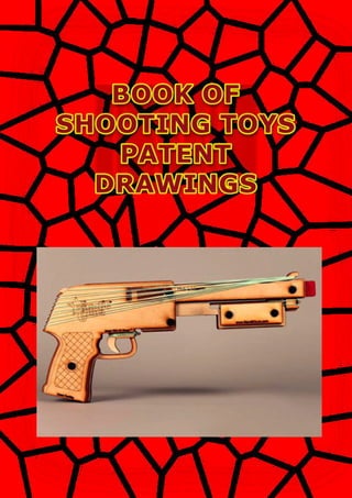
Book of shooting toys patent drawings , rubberband guns , cannon toys , cap guns , pellet guns , nerf guns , paint ball guns

Recomendados
Mais conteúdo relacionado
Mais procurados
Mais procurados (20)
Destaque
Destaque (20)
Semelhante a Book of shooting toys patent drawings
Semelhante a Book of shooting toys patent drawings (10)
Mais de Toz Koparan
Mais de Toz Koparan (13)
Último
Último (20)
Book of shooting toys patent drawings
- 2. TOY CANNONS PELLET GUN RUBBERBAND GUNS NERF GUNS AIR GUNS BALL GUNS PAINT BALL GUNS CAP GUNS
- 3. United States Patent [191 Traweek [11] 4,155,342 [451 May 22, 1979 [54] LASSO GUN [76] Inventor: Lowell E. Traweek, 8392 Snowbird ' Dr., Huntington Beach, Calif. 92646 [21] Appl. No.: 847,705 [22] Filed: . Nov. 2, 1977 [51] Int. Cl.2 ................................................ F4113 7/00 [52] US. Cl. ........................................ 124/27; 124/36; 124/41 A; 119/153 [58] Field of Search ............... 124/1, 16, 35, 36, 41K; ' 43/8; 119/153 [56] References Cited U.S. PATENT DOCUMENTS 2,732,647 l/1956 Byars .............. ......................... 43/8 2,891,342 6/1959 Grablc et al. .. 124/16 X 3,160,977 12/1964 Kickliter l24/36X 3,949,514 4/1976 Ramsey ............................ 119/153 X Primary Examiner-Richard C. Pinkham Assistant Examiner—William R. Browne Attorney, Agent, or Firm-K. H. Boswell [57,] ABSTRACT A lasso gun used in accurately propelling a lasso toward a target is described. The lasso gun has a barrel. Com municating along the longitudinal axis of the barrel is a piston which has a front lasso holder attached. The barrel is provided with a spring. When the piston is slid from the discharge end of the barrel towards the other end, the spring ‘is put under tension and when released .the piston is forcibly slid back towards the discharge end of the barrel. An arm is pivotally mounted on the underside of the barrel. The arm has a rear lasso holder attached to its free end. The loop of a lasso is placed around both the front and rear lasso holders, the piston pushes away from the discharge end of the barrel tens ing the spring and‘the arm is swung back away from the discharge end ofthe barrel. When released or fired, the piston is propelled forward and the forward motion transferred to the lasso loop. This causes the rear end of the loop to pull the arm and the bottom end of the loop attached to it forward in an arc. After the piston reaches the end of its slide and abruptly stops, the lasso is pro pelled off of the front and rear lasso holders towards a target. 10 Claims, 7 Drawing Figures 77121111111115
- 4. US. Patent May 22, 1979 Sheet 1 of2 4,155,342 N.leu?lh Qm.umNRNW mm“m A
- 5. US. Patent May 22, 1979 Sheet 2 of2 4,155,342
- 6. Note: Within nine months of the publication of the mention of the grant of the European patent in the European Patent Bulletin, any person may give notice to the European Patent Office of opposition to that patent, in accordance with the Implementing Regulations. Notice of opposition shall not be deemed to have been filed until the opposition fee has been paid. (Art. 99(1) European Patent Convention). Printed by Jouve, 75001 PARIS (FR) (19)EP2208959B1 TEPZZ Z8959B_T (11) EP 2 208 959 B1 (12) EUROPEAN PATENT SPECIFICATION (45) Date of publication and mention of the grant of the patent: 13.03.2013 Bulletin 2013/11 (21) Application number: 10150722.6 (22) Date of filing: 14.01.2010 (51) Int Cl.: F41B 11/646 (2013.01) F41B 11/89 (2013.01) (54) Paper bullet firing pistol toy Papiergeschosse abfeuernde Spielzeugpistole Jouet de pistolet tirant des balles de papier (84) Designated Contracting States: AT BE BG CH CY CZ DE DK EE ES FI FR GB GR HR HU IE IS IT LI LT LU LV MC MK MT NL NO PL PT RO SE SI SK SM TR (30) Priority: 20.01.2009 JP 2009009584 (43) Date of publication of application: 21.07.2010 Bulletin 2010/29 (73) Proprietor: Agatsuma Co., Ltd. Tokyo (JP) (72) Inventor: Funaki, Shotaro Tokyo (JP) (74) Representative: Skone James, Robert Edmund Gill Jennings & Every LLP The Broadgate Tower 20 Primrose Street London EC2A 2ES (GB) (56) References cited: FR-A- 918 278 FR-A- 991 950 US-A- 2 490 991 US-B2- 6 669 530
- 7. EP 2 208 959 B1 16
- 8. EP 2 208 959 B1 17
- 9. EP 2 208 959 B1 18
- 10. EP 2 208 959 B1 19
- 11. EP 2 208 959 B1 20
- 12. EP 2 208 959 B1 21
- 13. EP 2 208 959 B1 22
- 14. EP 2 208 959 B1 23
- 15. EP 2 208 959 B1 24
- 16. Aug. 25, 1953 c. L. PARRIS 2,649,849 I - ' PISTOL CONSTRUCTION Filéd July 17,1950 - @cz/LFarris"
- 17. Dec. 3, 1957 s. M HALL ’ 2,815,212 l PUNCH GUN Filed March 6, 1956 INVENTOR. ATTE RN EYB
- 18. Feb. 27, 1962 E. BENKOE 3,022,779 TOY GUNS Filed June 14, 1960 2 Sheets-Sheet 1 R Ea.1. / Z5 Q ‘Q Q [Q g {Q § E . INVENTOR ‘ ERWIN BENKOE @w . BY AMA/Mil 3w”ATTORNEY S
- 19. Feb. 27', 1962 Filed June 14, 1960 E. BEN KOE TOY GUNS , 3,022,779 2 Sheets-Sheet 2 127/4 III/IIIII'II'" INVENTOR ERWW .BENKDE BY QTGZgOéNEYS
- 27. 2,446,698Aug. 10, 1948. M. M. FUJIWARA TOY CAP GUN 4 Sheets-Sheet 1 Filed Dec. 18, 1946 I11 renter M. Fujiwara
- 28. 2,446,698Aug- 10, 1948- M. M. FUJIWARA TOY CAP GUN 4 Sheets-Sheet 2Filed Dec. 18, 1946 41 11:13:: 1-0 v Inventor ack . Fujiwara
- 30. Aug. 10, 1948. M. M. FUJIWARA 2,446,698 TOY CAP GUN Filed Dec. 18, 1946 4 Sheets-Sheet 4 lulu/im / Mack M. Fujiwara 45 Fig.I0.
- 32. May 12, 1953 H. L. LANGOS 2,637,941 ‘ ' PAPER BURSTER GUN Filed Dec. 12,v 1949 2 Sheets-Sheet l 1NVENTOR.
- 33. May l2, 1953 H. L. LANGOS PAPER BURSTER GUN 2,637.941 Filed Deo. l2, 1949 2 Sheets-Sheet 2 . 7
- 34. Nov. 17, 1953 R. D. PARRY ` 2,659,172 FIRING MECHANISM FOR PIsToLs Filed July 14, 195o Ä log.j INVENTOR ?ZaberÍ ä Parr]BY
- 35. y April 12, 1955 A. R. MILLS 2,706,067 Toy PIsToLs Filed Dec. l, 195o s sheets-sheet 1 HHH
- 36. Apri] 12, 1955 A. R. MILLS 2,706,067 TOY PIsToLs Filed Dec. l, 1950 3 Sheets-Sheet 2 // |l ß 619 @5 6% » a@
- 37. 2,706,067A. R. MILLS TOY PISTOLS April 12, 1955 5 sheéts-sheet 3 Filed Dec. l, 1950 ump' W.
- 38. Jan. 3, 1956 K. w. FRYE 2,729,011 AUTOMATIC CAP GUN MECHANISM Filed Sept. 27. 1954 5 Sheets-Sheet 1 KENNETH W. FRYE, INVENTOR HUEBNER, BEEHLER, WORREL £9‘ HERZIG, ATTORNEYS.
- 39. 2,729,011Jan. 3, 1956 K. w. FRYE ' AUTOMATIC CAP GUN MECHANISM Filed Sept. 27, 1954 I5 Sheets-Sheet 2 E,R6, YRwus.ammHRHmEEM{JUN[WVEH0 _8.“l..3..QmBEN Ill__..||_LHR14a____,___TELv._®__ENBM QKRmm;%cN._W0 KHW BY 51
- 40. Jan. 3, 1956 Filed Sept. 27, 1954 K. W. FRYE 2,729,01 1 AUTOMATIC CAP GUN MECHANISM 60 3 Sheets-Sheet 3 KENNETH W. FRYE,INVENTOR HUEBNER, BEEHLER, WORREL £9‘ HERZIG, ATTORNEYS. Y WM
- 41. Aug. 18, 1959 ' K. J. sTALLER 2,899,765 TOY CAP GUN WITH LONGITUDINALLY MOVABLE ACTUATOR Filed Nov. 5, 1956 ` 3 Sheets-Sheet 1 «n»î... Yul on NÑ ` E N m
- 42. Aug. 18, 1959 K. J. sTALLER I ' 2,899,766 TOY CAP GUN WITH LONGITUDINALLY MOVABLE ACTUATOR Filed Nov. 5, 19564 5 Shee‘cs-Sheet~2A
- 44. Oct. 2, 1923.’ - 1,469,610' I G. USTYNIK' I ' TOY GUN Filed April V17, 1923 Z”? 1% I
- 45. 1,572,350Feb. 9 , 1926; F. c. EcKER JREPEATING GUN FOR SHOOTING ELASTIC BANDS Filed Oct. 30, 1925 J.w INVENTOR. __BY
- 46. 1,723,554B. F. M ALOTT~ Aug. 6, 1929. Filed Nov. 22, 1927 (5.. i794 ‘ /2~ // wrmess: ATTO R N EY
- 47. Oct. 1, 1929.’ - T. E. WEBB 1,729,917 TOY PISTOL Filed Sept. 17, 1928 am A > ' INVENTOR. /7X T/mmas E. Web5. O BY / v. 4' I ‘ A TTORNEY. 24 GD 25
- 48. June 9, 1931. .1. R. MCFARLAND 1,809,203 ‘ _ REPEATING GUN FOR SHOOTING ELASTIC BANDS Filed March 17, 1930 2" Sheets-Sheet l v A? W i _ Inventor f1? </_%C ar/amd $5 ‘ ' 1392mmAttomcy
- 49. ‘ June 9, 1931. J. R. MGFARLAND 1,309,208 . ' REPEATING GUN FOR SHOOTING ELASTIC BANDS ‘ Filed March 1'7, 1930 2 Sheets-Sheet 2 Inventor Attorney _
- 50. 1,821,381B` B. JGERKENSept. 1, 1931. TOY GUN Filed Aug. _23. 1930 .........-. INVENTOR A 5.5’. Gerkfn MGM??_9.13mATTORN EY
- 51. Feb, 9, M32. s. c. MOUNTJOY ET AL L8449l73 TOY PISTOL Filed Dec. 22, 1928
- 52. May 23, 1933-v P. w. BEAUCHAMP ET AL 1,909,927 REPEATING RUBBER BAND RIFLE _ I Filed Aug. 27, 19,52 -| ATTORNEYS. '.
- 54. ¿008,595M. A. REEDÄußy B6, 1935. TOY GUN Filed DSC. 16, 1953
- 55. Nov. 19, 1935. , F. HAGEN 2,021,776 TOY GUN Filed Feb. 28, 1935 $2», -
- 56. 2,098,001Nov._2, 1937. L. GAGNON ET AL RUBBER BAND GUN Filed Nov. 17, 1936 INVENTORS laws GAGA/0Ma??/vm/A/f6mm 0000000 0000000000.ooooooooooéoono?owwwnwwowpobovosv.‘ 16 1'5 0 / _/v 17 ___._____________
- 57. April! 25, 1950 A. E. STONE 7 2,505,591 TOY RUBBER BAND PROJECTING GUN Filed 'June 27, 1945
- 58. May 1, 1951 E. |_. SIDERS 2,550,873 Toy REPEATING RUBBER BAND PISTOL ' Filed Jan. 26, 1948 ’ 2 Sheets-Sheet l 9-4115 ., INVENTOR. ELLIS ‘L, EIDERS _BY I ATTURAZE
- 59. May 1, 1951 E. 1.. SIDERS 2,550,873 TOY REPEATING RUBBER BAND PISTOL Filed Jan. 26, 1948 2 Sheets-Sheet 2' INVENTOR. ELLIS L, 515E515 BYQMQ/ ' ATTURNE:
- 60. Oct. 30, 1951 ‘ ' A_ G_ HERR|NG I 2,573,142 REPEATING RUBBER BAND TOY_ GUN Filed June 16, 1947 ?vl‘lur G, lqerrr'irlg INVENTOR. ATTORN EY
- 61. NOV. 27, |___ D_ wRlgHT. ETAL 2,576,248 REPEATING RUBBER BAND TOY GUN I ' Filed April 7, 1947 " . Lox/1s p, WEIGHT ,
- 62. INVENTOR lfiz’emazz TZ’QyZesan Jr ATTORNEY 2,625,147 BY. rid§%W F. T. EAGLESON, JR REPEATING TYPE ELASTIC BAND PROJECTOR Filed April 7, 1951 Q Jan. 13, 1953
- 63. 2,676,581April 27, 1954 a. B. MOORE RUBBER BAND GUN Filed Aug. 10, 1951 g.A INVENTOR 3/2.4IE 15’. Moo/PE BY ,y/s ATTORNEY
- 64. 2,689,558 sept. 21, 1954 _ R. E. SEALER ETAL REPEATING RUBBER BAND PISTOL Filed sept. 15. l1952 fIl,»lll/IIIA,lll/1111111141554/f//lllrf/r; INVENToRs ~ ff Sfmt-R ßa/mzp Ä? «50077 Arran/vir
- 65. Jan. 10, 1956 ' R. E. HICKS 2,730,094 REPEATING TOY GUN Filed Oct. 11, 1952 INVENTOR. 370V 5 f/lC/‘R‘S (Quill.‘TL/MAJAWOENEYG.
- 66. April 10, 1956 J. s. ARNOLD 2,741,238 TOY GUN Filed May 26, 1954 2 Sheets-Sheet 1 % Joseph .5’. Arnold INVENTOR. BY MMyjmaifghm
- 67. 2,741,238April 10, 1956 J. s. ARNOLD TOY GUN 2 Sheets-Sheet 2Filed May 26, 1954 28 60 52t 24‘H; ‘ Joseph 5‘. Arnold 11W ‘ENTOR.
- 68. May 28, 1957 E. H. KOELLER 2,793,635 ' TOY sun Filed Oct. 13, 1953 2 Shgeta‘Sheet 1
- 69. May 23, 1957 EH. KOELLER 2,793,635 TDY cuu Filed on. 13, 1953 2 Sheets-Sheet 2
- 70. March __4, 1958 ‘ s. 'r. BURLE'Y, JR, ETAL 2,825,322 ' REPEATING TOY GUN l Filed July 23, 1954 ‘ | '1'.’ .. M 1/ Samuel T. Bur/e], J1: Coy V. Payton INVENTORS B; 24mm » “#WFM,» - 30
- 71. March 24, 1959 A. L. kucH 2,878,802 RUBBER BAND GUN Filed Aug. 29, 1957 2 Sheets-Sheet l Fig.5 ' Allan L. Kuch INVENTOR. £40m
- 72. March 24, 1959 ' A. |_. KUCH 2,878,802 RUBBER BAND GUN Filed Aug. 29, 1957 ‘ 2 Sheets-Sheet 2 44 F1'92 20 Allan L. Kuch INVENTOR. BY '
- 73. 2,917,037Dec. 15, 1959 R. L. HENDERSON REPEATING RUBBER BAND GUN 2 Sheets-Sheet 1Filed April 19, 1957 m H h ‘Mu .lllliizl MmKWJ (Q1 ,, INVENOR. J pKUZ%,/w%
- 74. Dec. 15, 1959 R. |_. HENDERSON 2,917,037 REPEATING RUBBER BAND GUN Filed April 19, 1957 2 Sheets-Sheet 2 / QéjgéIiJVENTOR. /
- 75. Jan. 28, 1964 H. J. ASHLEY 3,119,385 REPEATING GUN FOR SHOOTING ELASTIC BANDS Filed March 19, 1962 3 Sheets-Sheet 1 7 4M FIGURE 1 1 1 :5 Jib/‘Z 2 ' <_A ' 7 r”? £341 4 . ' 15 4EE g . 33 E __/ 9a 9 -+J_A_ 1/ 1 FIGURE 2 ___J FIGURE 3 3,’ a 12 12 6 10 15 7 5 I, A 5 sllli d‘ : nkMAA/‘l ‘5 11 5/ 9a 9 1p 9 1 FIGURE 4 FIGURE 5 1 Howard J As/z/gy INVENTOR. BY jg5M 01[011mg]
- 76. Jan. 28, 1964 H. J. ASHLEY 3,119.,385 REPEATING GUN FOR SHOOTING ELASTIC BANDS Filed March 19, 1962 3 Sheets-Sheet 2 FIGURE 6 2“ FIGURE 8 20 Howard J. Ask/6y INVENTOR. BY 95 $3M
- 77. Jan. 28, 1964 H. J. ASHLEY 3,119,385 REPEATING GUN FOR SHOOTING ELASTIC BANDS Filed March 19, 1962 *WB > 22/E5 W2 16 Q]; FIGURE 10 22 FIGURES FIGURE 11 Howard J. Ashley ziffarznkgy 3 Sheets-Sheet 3‘
- 78. o. J. LILLEOREN, JR., ET AL 3,408,996Nov. 5, 1968 RUBBER BAND _GUN 2 Sheets-Sheet lFiled May~ 5, 1965 AGENT
- 79. Nov. 5, 1968 o. J. LILLEOREN, JR., ET AL 3,408,995 RUBBER EAND _GUN Filed May E, 1965 2 Sheets-Sheet 2 30I OLE J. LILLEOREN, JR. CHRIS G. PAZEOTOPOULOS ROBERT J. SHIDEK INVENTORS lli E AGENT BY
- 80. 3,494,345E. G R! FFITHSFeb. 10, 1970 REPEATING SELF-PROJECTING ELASTIC BAND TYPE GUN Filed April 22, 1968
- 81. June 2, 1970 L. 5. HOUSE 3,515,387 TOY GUN FOR DISCHARGING ELASTIC BANDS Filed - July 26, 1.968
- 82. United States Patent [72] Inventor Mitsuo Endo 1012 Barnisdale Road, Birmingham, Alabama 35232 [21] Appl. No. 723,439 [22] Filed April 23, 1968 [45] Patented Oct. 27, 1970 [54] RUBBER BAND GUN 7 Claims, 4 Drawing Figs. [52] U.S.Cl............. ... ...................................... .. 124/18, 124/45, 124/35 [51] lnt.Cl....................................................... .. F4lb 7/02 [50] Field ofSearch.......................................... .. 124/18, 19, .,~ 16, 35. 41 v[56] References Cited UNITED STATES PATENTS 1,751,488 3/1930 Meyer ........................ .. 124/18 l11l3,53.6,055 - 11/1932 Saxton ........................ ..1,887,520 124/18 FOREIGN PATENTS 263,685 12/1949 Switzerland ................ .. 124/18 Primary Examiner— Richard C. Pinkham Assistant Examiner—william R. Browne Attorney-Clarence A. O’Brien and Harvey B. Jacobson ABSTRACT: An elongated resilient member is slidingly ; mounted between its ends in a passage provided in the grip of I a toy-type rubber band gun. The laterally bent forward end of 3 said member is anchored in the barrel and provides a normally cocked trigger. The terminal rearward end provides a band i retaining but releasable catch while the speci?cally bowed median portion is fashioned into a loop which holds a reserve supply of ready-to-use extra bands. This gun is adapted for use i by the youngster who is intrigued by a “pistol" or the like that shoots rubber bands and carries a reserve supply for instant re loading.
- 83. Patented Oct. 27, 1970 3,536,055 ' Mifsuo Endo INVENTOR. BY‘wmwg'ti?gw
- 84. United States Patent Vodinh - [151 3,693,609 [451 Sept. 26, 1972 I [72] Inventor: - [54] REP-EATING TYPE ‘RUBBER BAND, PROJECTING PISTOL Hien Vodinh, 6418 Covington Road, . Fort Wayne, lnd. 46804 [22‘] Filed: June17, 1971 [21] Appl.No.: 154,022 [52] U.S. Cl. ....................'...'.l24/l9,'l24/48, 124/41, , , ‘ 124/35 [51] I Int. Cl........................................ ..... ..F4lb 7/02 [58] Field ofSear'ch.................l24/l9_,-l8,35,41,48 [56] References Cited UNITED STATES PATENTS 1,868,312 7/1932 Coventry ................;....l24/l8 2,001,267 5/1935 Ross.............;..............124/19 Primary Examiner-Anton O. Oechsle Assistant Examiner—William R. Browne Attorney-Woodard,‘ Weikart, Emhardt & Naughton [57] ABSTRACT A repeating toy pistol for shooting rubber bands. The pistol has a cylinder structure which is rotationally in . dexed with each trigger pull. Both the tripper-pull mo tion and the trigger-retum motion are utilized to pro vide the indexing motion of the barrel thereby provid ing a positive, relatively lengthened indexing motion of the barrel with a limited, relatively short trigger mo tion. The pull of the trigger causes a slide to engage and lift a rubber band off of a ridge on the cylinder. , 8 Claims, 9 Drawing Figures‘
- 86. United States Patent [191 Darnell {111 3,757,760 [451 Sept. 11, 1973 [54] [76] [221 [21] [52] [51] [581 [56] 2,001,267 TOY GUN WITH ROTATING MAGAZINE FOR DISCHARGING ELASTIC BANDS Wayne Lee Darnell, Rt. 6, Hwy. 79, Clarksville, Tenn. 37040 Filed: June 14, 1971 Appl. No.: 152,544 Inventor: US. Cl....................... .. 124/19, 124/48, 124/35 Int. Cl. ......................... .. F4lb 7/02, F4lb 7/09 Field 01' Search ................. .. 124/18, 48, 19, 41, 124/16 References Cited UNITED STATES PATENTS 5/1935 Ross .................................... .. 124/19 Primary Examiner—Richard C. Pinkham Assistant Examiner—-William R. Browne Attorney—-—Harrington A. Lackey [57] ABSTRACT A toy gun having a handle member and an elongated spindle rotatably mounted upon the handle member. The spindle is provided with equally spaced front radial projections and equally spaced aligned rear radial pro jections for receiving thereover stretched rubber bands. A trigger member on the handle member is pro vided with a cam rod biased forward into operative en gagement with a cam surface on each rear radial pro jection for simultaneous rotation of the spindle and re moval of the elastic band from the rear projection. Upon de-actuation of the trigger means, the cam rod moves into operative engagement with the next succes~ sive rear projection. 5 Claims, 7 Drawing Figures
- 87. 3.757. 760PAIENIEUSEH 1 I975 INVENTOR : Way/v £55 Dam/£44 BY A ORNEY
- 88. Unite States atent r191 Skillern [111 3,812,833 [451 May 28, 1974 1541 ELASTIC BAND GUN John A. Skillern, 132_State St., Framingham, Mass. 01701 [22] Filed: Jan. 31, 1972 [21] Appl. No.: 221,960 [76] Inventor: [52] US. Cl. .............. .. 124/19, 124/35 R, 124/30 R [51] Int. Cl. ........................................ F41b 7/02 [58] Field of Search ....... ..124/19,17,18, 35 R, 41, 124/31, 1; 33/265, 244; 89/36 E [56] References Cited UNITED STATES PATENTS 2,289,490 7/1942 Fisher ................................. .. 1-24/19 2,550,873 5/1951 Siders . . . . . . . . . . . . . .. 124/19 2,697,425 12/1954 McElveenunr. . . . ... 124/19 3,119,385 l/l964 Ashley ................................ 1. 124/19 Primary Examiner~Richard C. Pinkham Assistant Examiner—Williarn R. Browne Attorney, Agent, or ~Firm--Wolf, Green?eld & Sacks [57 ] ABSTRACT An elastic band gun having a plurality of pivotally mounted releasers which are serially located from front to back on the stock. Each relcaser is adapted to support the rear end of a stretched elastic band and upon actuation to release the band at a level above that of the tops of any forwardly located releasers A spring action powered, manually cocked, escapement type sequencing system responsive to actuation of the trigger works either semi-automatically 'or fully automatically to free the releasers to discharge the bands. In another form, the bands are retained in notches, and scrapers controlled by the sequencing system free the bands from the notches to discharge them. A combination safety shield and sighting ‘device is designed to capture rearwardly discharged elastic bands. ' ' > > 15 Claims, 17 Drawing Figures
- 94. United States Patent [19] [11] 3,919,996 McAlister [45] Nov. 18, 1975 [54] REPEA'HNG SELF PROJECTING BAND 2,697,425 12/1954 McElveen ........................... .. 124/19 TYPE APPARATUS 3,812,833 5/1974 Skillern ............................... .. 124/19 [76] Inventor: Edgar O. McAlister, 9810 E. Broadway, Tucson, Ariz. 85710 [22] Filed: _ May 22, 1974 [21] Appl. No.: 472,129 [52] US. Cl......... .. 124/19; 273/D1G. 16; 124/30 R; 124/35 [51] Int. Cl.2 .......................................... .. F41B 7/02 [58] Field of Search .... 124/19, 26, 27, 30 R, 28, 124/29, 35, 34, 41; 2_73/D1G. 9 [56] References Cited UNITED STATES PATENTS 2,573,142 10/1951 Herring ............................... .. 124/19 Primary Examiner-Richard C. Pinkham Assistant Etaminer-William R. Browne Attorney, Agent, or Firm-H. Gordon Shields [57] ABSTRACT Rubber gun apparatus is disclosed which shoots a plu rality of rubber bands, or the like, from consecutive > pulls of a trigger using a sliding bolt movable by trig ger movement to release pivoting studs to which the rubber. bands are af?xed. The sliding bolt is unbiased and is manually movable to the rear of the apparatus. This movement causes the sliding bolt to disengage the studs and cause them to pivot downwardly to a rubber band releasing position. 11 Claims, 5 Drawing Figures 30
- 96. United States Patent [191 Sundstrom [11] 4,223,658 [45] Sep. 23, 1980 [54] ELASTIC BAND PROJECTING TOY GUN Paul Sundstrom, 53 Barney St., Gladstone, Queensland, 4680, [76] Inventor: Australia [21] Appl. No.: 924,190 [22] Filed: Jul. 13, 1978 [30] Foreign Application Priority Data Jul. 18, 1977 [AU] Australia .............................. PDO883 [51] Int.(:1.3 .............................................. .. F41B 7/02 [52] U.S. Cl. .............................. 124/19; 124/80 [58] Field of Search ................... 124/19, 18, 17, 35 R, 124/41 R, 48 [56] References Cited U.S. PATENT DOCUMENTS 1,724,271 8/1929 Fisher .................................... 124/19 1,826,053 10/1931 Carpenter .. 124/19 1,935,287 11/1933 Damico 124/19 1,944,377 l/l934 Taylor ...... 124/18 2,741,238 4/1956 Arnold ................................... 124/19 Primary Examiner-Richard C. Pinkham Assistant Examiner-‘William R. Browne Attorney, Agent, or Firm—Her1ry M. Bissell [57] ABSTRACT A toy gun which is capable of?ring a plurality ofelasti cized bands, either singularly'or in rapid succession, and which is operative so that each one of a plurality of elasticized bands is stretched under the tension of its own elasticity along a projectile path longitudinal with the gun between a point of anchorage at the forward end of the gun and a rotatable escapement wheel at the rearward end of the gun so that, when the escapement wheel is permitted to rotate under the in?uence of a rotational bias provided by the force of the previously loaded elasticized bands upon the release of a trigger mechanism, the elasticized bands are consecutively released from engagement with the escapement wheel to be propelled along the projectile path and forwardly of the gun. The wheel includes a plurality of spaced apart radially extending sections that have successively increasing radii over substantially the entire outer-most periphery of all of the sections. 8 Claims, 5 Drawing Figures
- 101. [11] 4,308,850 Jan. 5, 1982 United States Patent [19] ‘Hunter [45] 124/19 124/19 99AA4422ll [54] MULTIPLE ELASTIC BAND PROJECTOR 2,008,595 7/1935 Reed2,021,776 11/1935 Hagen [76] Inventor: James P. Hunter, Rte. 7, BOX 255E, 2,576,248 11/1951 Wright et a1_ 1 Denham Sprmgs, La- 70726 3,119,385 1/1964 Ashley[21] Appl. No.: 42,519 Primary Examiner—Richard J. Apley - _ Assistant Examiner-William R. Browne [22] Flled' May 25’ 1979 Attorney, Agent, or Firm——-R0y, Kiesel, Patterson & [57] ABSTRACT F41B 7/02 .. 124/19; 124/35 R;[52] us. c1. 124/41 R 124/19, 18, 35 R, 40, An elastic band projector is disclosed having a loading and ?ring mechanism for sequentially ?ring more than one elastic band without stopping to reload the elastic bands on the projector. ’ [58] Field of Search 124/41 R _ ‘References Cited us. PATENT DOCUMENTS 1,821,381 9/1931 Gerken .1561 l 5 Claims, 1 Drawing Figure.. 124/19
- 103. . v, United States Patent [191 [111 »LoBiondo ' [45] Apr. 12, 1 83 [54] RUBBER BAND Primary Examiner-Richard C. Pinkham . . Assistant Examiner—William R. Browne [76] Inventor' gllclgklitytll?gugdr{281373 19th Ave" Attorney, Agent, or Firm-Robert D. Farkas [21] Appl. No.: 245,425 [57] ABSTRACT [22] Filed: Mar. 19, 1981 A rubber band ri?e for shooting one or a plurality of 3 rubber band members generally includes a body having ' ' ' ' ' ' ' ' ' ' ' ' ' ' ' ' ' " a forward barrel portion and a rear shoulder portion _. . ................................................ having a plurality of horizontal grooves disposed l f h ................l241,18,41R,35R _ Fla d o seal-CR f C‘ d/ 9 therein, one end of each of the rubber band members e erences 'te U.S. PATENT DOCUMENTS 1,909,927 5/1933 Beauchamp et al. ................. 124/19 2,098,001 11/1937 Gagnon et a1. ....... 124/19 2,576,248 11/1951 Wright et al. 124/19 2,625,147 1/1953 Eagleson ................... 124/19 2,878,802 3/1959 Kuch ......... 124/19 2,917,037 12/1959 Henderson 124/19 3,494,345 2/1970 Griffiths ................................ 124/19 FOREIGN PATENT DOCUMENTS 1159349 7/1969 United Kingdom .................. 124/19 being disposed in one of the horizontal grooves in the forward end wall, a slide mechanism being movably disposed on the forward barrel portion, the slide mecha nism including atop and a,pair of downwardly extend ing walls, an upper surface ofthe top of the slide mecha nism having a plurality-of notches therein, the other ends of the rubber bands being disposed in the notches, and a mechanism for locking the slide mechanism in a ?xed position upon the barrel portion of the body. 3 Claims, 3 Drawing Figures
- 105. United States Patent [191 [11] Patent Number: ' 4,554,904 Endo [45] Date of Patent: Nov. 26, 1985 [54] TRIGGER ASSEMBLY FOR RUBBER BAND 819013 8/1959 United Kingdom .................. 124/27 GUN Primary Examiner—Paul E. Shapiro [76] Inventor: Mitsuo Endo, 1120 S. State, Attorney, Agent, or Firm—Harvejy B. Jacobson Clear?eld, Utah 84015 [57] ABSTRACT [21] Appl' No‘: 692’070 A toy rubber band gun having a gun body de?ning an [22] Filed; Jam 15, 1935 imitation barrel, a stock at the back of the barrel, and a _ handle depending from the stock. A trigger element in C1Cl4 iiiiiiiiiiiiiiiiiiiiiiiiiiu the form of a resilient wire has a forward end pivotally [58] F.‘ l'd """ """"""" 4A8 19’ 35 R 37 mounted on a pin in the stock, a trigger portion extend~ 1e 0 care """""""""" ’ 124/45’ 27’ ing out through a slot on the bottom of the stock, an ’ elongate portion extending from the trigger portion [56] References Cited upwardly through the handle, and a loop portion ex U.S. PATENT DOCUMENTS 212,826 3/1879 Weaver ................................. 124/27 1,024,374 4/1912 Stambaugh . 124/35 R UX 1,234,163 7/1917 Henderson .. .. 124/35 R UX 2,594,527 4/1952 Wechsler .......... 124/37 X 3,536,055 10/1970 Endo . . . . . . . . . . . . . . . . . . . .. 124/18 4,033,313 7/1977 Ryan .......................... 124/35 R X FOREIGN PATENT DOCUMENTS 877421 8/1971 vCanada .................................. 124/27 66 tending from the elongate portion upwardly behind the handle, the loop portion terminating in a hooked tip biased against the back of the stock to form a retainer for a rubber band stretched along the length of the stock and barrel so that pulling back on the trigger portion draws the hooked tip away from the stock and releases the band. The trigger element is characteristically bent to enable its tension to be adjusted. 10 Claims, 4 Drawing Figures
- 107. United States Patent [19] Miller [54] REPEATING RUBBER BAND PISTOL Tony Miller, 1303 E. Kenwood Ave., Anaheim, Calif. 92806 [211 App]. No.: 906,886 [22] Filed: Sep.15,1986 [51] Int. cm ................................................ F41B 7/02 [76] Inventor: [52] US. Cl. ............................... 124/19; 124/48 [58] Field of Search ................ 124/48, 35 R, 19, 41 [56] References Cited U.S. PATENT DOCUMENTS 2,001,267 5/1935 Ross ...................................... 124/48 3,549,148 12/1970 Schloss 124/35 R 3,556,072 1/1971 Levin . . .. . . . . .. .. 124/35 R 3,693,609 9/1972 Vodinh .. ... .. . .. . .. 124/35 R 3,757,760 9/1973 Darnell ............................. l24/35R Primary Examiner-Richard C. Pinkham Assistant Examiner—T. Brown Attorney, Agent, or Firm—-Ben E. Lofstedt [57] ABSTRACT A repeating rubber band pistol for shooting elastic band and the like, including a pistol frame with handle and a 4,676,219 Jun. 30, 1987 [11] Patent Number: [45] Date of Patent: pair of support arms extending upwardly from the frame, the support arms having a pair of complemen tary holes therein, a hand crank with a rotary spindle thereon adapted to be mounted in the pair of support arms through the pair ofholes therein and adapted to be freely movable therein, a cylindrical magazine with a plurality of radially-extending elongated arms disposed circumferentially about a centrally-arranged spindle member having a central aperture therein for mounting a plurality of stretched rubber bands thereon to hold in readiness for shooting said rubber bands, and a solid cylindrically shaped spindle mounted on the frame for wardly of the handle and the support arms and adapted to freely receive the apertured magazine thereon, whereby when a string is anchorably secured to the spindle ofthe hand crank and the string is secured medi ately about the body of one of the stretched rubber bands and the hand crank operated, the string lifts the rubber band from its mounting causing it to be shot from the gun. 3 Claims, 7 Drawing Figures
- 110. United States Patent 1191 Small 4,800,864 Jan. 31, 1989 [11] Patent Number: [45] Date of Patent: [54] REPEATING RUBBER BAND PROJECI'ING GUN [76] Inventor: Steve E. Small, 5811 E. Waverly, Tucson, Ariz. 85712 [21] Appl. No.: 100,207 [22] Filed: Sep. 23, 1987 [51] Int. 01.4 ................................................ F41B 7/02 [52] us. 0. ................................... 124/19; 124/35 R; 124/48 [58] Field of Search ................... 124/18, 19, 35, 41 R, 124/48; 74/142 [56] References Cited U.S. PATENT DOCUMENTS 2,550,873 5/1951 Siders .................................... 124/19 2,741,238 4/1956 Arnold .. . . . .. . . . .. .. 124/19 2,917,037 12/1959 Henderson 124/19 3,515,387 6/1970 House ........... 273/101 3,693,609 9/1972 Vodinh 124/19 3,757,760 9/1973 Darnell 124/19 4,676,219 6/1987 Miller .. . . . .. .. . .. 124/19 Primary Examiner-Randolph A. Reese Assistant Examiner-John A. Ricci [57] ABSTRACT A toy gun for shooting rubber bands in rapid succession includes a rotating cylinder onto which the rubber bands initially are loaded one-by-one. Rotation of the cylinder to effectuate initial loading of the rubber bands stretches an elastic cord which later rotates the cylinder in the opposite direction as rubber bands are tired in succession. A plurality of pivotal hooks disposed on the rear portion of the rotating cylinder each engage the rear end of a stretched rubber band, the forward end of which is retained by a corresponding hook disposed on the front portion of the cylinder. An actuator/stop element responsive to a trigger operates to depress or pivot the hook and rubber band aligned with the ac tuator/stop element, shooting that rubber band. The depressed or pivoted hook is retained so that when the trigger is released, the actuator/stop element moves away from a rotation limiting stop connected to the depressed or pivoted book. The pre-tensioned elastic cord rotates the cylinder to align the next rubber band with the actuator/stop element. A rotation limiting stop connected to the next hook abuts the actuator/stop element, at which time the trigger is to be pulled again to tire the next rubber band. 9 Claims, 2 Drawing Sheets
- 113. 0 United States Patent [191 [11] Patent Number: 4,827,892 Vandermeide [45] Date of Patent: May 9, 1989 [54] TOY GUN FOREIGN PATENT DOCUMENTS [76] Inventor: Benjamin Vandermeide, 3904 430799 6/1935 United Kingdom .................. 124/19 Hallmark Dr., Salt Lake City, Utah 458660 12/1936 United Kingdom .................. 124/19 84119 Primary Examiner-Randolph A. Reese 21 A L N ‘z 200 238 Assistant Examiner-John Ricci [ ] pp 0 ’ Attorney, Agent, or Firm-B. Deon Criddle [22] Fll?dl May 31, 1988 [57] ABSTRACI ‘ [51] Int. cu ............................ F418 7/02; F41F 7/00 A multiple ?ring elastic shooter toy including a handle, [52] US. Cl. ........................................ 124/19; 124/18; 9rod which may take the form of a barrel and having a 124/35 R notched end to receive lengths of elastic members and a [58] Field of Search ................ 124/18, 19, 35 R, 41 R receiver section interconnecting the handle and the rod. ' The receiver section is of generally U-shaped cross-sec [56] References Cited tion and has a web at one side ofthe shooter and top and U S PATENT DOCUMENTS bottom legs. Spaced apart slots are formed in the web ' ' ' and partially into the legs ofthe receiver to accept other Iliad?“ --------------------------------~ lengths of the elastic members. A snubber post projects I 1 ams """"""""""""" from the shooter toy at the side opposite the web and 1909927 5/1933 Beauchamp et a1‘ 124/19 forwardly of the slots in the direction of the rod and 2,021,776 11/1935 Hagen .. . .. .. ... ... ... .. . .. .. 124/19 f . . 2,065,580 l2/l936 Grawunder __ 124/19 serves as a 'sa ety against inadvertant release of 3,437,084 4/1969 Hyter . . ..... 1.. .. 124/19 Stretched elastw members 3,536,055 10/1970 Endo ... .. . .. ... .. 124/18 4,379,445 4/1983 Lobiondo .............................. 124/19 7 Claims, 1 Drawing Sheet
- 115. a O Umted States Patent [19] [11] Patent Number: 4,949,494 Mims [45] Date of Patent: Aug. 21, 1990 [54] REPEATING RUBBER BAND PISTOL 4,223,658 9/1930 Sundstrom ............................ 124/19 [76] Inventor: Donald B. Mims, 5665 Banks Rd., FOREIGN PATENT DOCUMENTS I Fm wc’nh' Te" 76140 73436 6/1917 Austria .................................... 42/54 [21] APPL No_; 436,440 439978 12/1935 United Kingdom .................. 124/19 [22] Filed; No“ 14’ 1989 Primary Examiner-Charles T. Jordan 5 Assistant Examiner-Richard W. Wendtland ClCi ----------------------n‘--------------- D.124/351 [57] ABSTRACT [58] Field of Search ................. 42/54; 124/17, 18, 19, A repeating rubber band pistol is shown which includes 124/31’ 35 R a frame having a barrel and a handle. A handle recess [56] References Cited houses a rotary magazine. A plurality of bands can be U S PATENT DOCUMENTS stretched between a barrel notch and engagement ' ' points on the rotary magazine. A trigger element is Brown ..................................... mounted the frame recess and allows Controlled 133109 """" movement of the rotary magazine to selectively release 1’955’9o0 4/1934 Bil-1:: 42/54 rubber bands in single ?re fashion with successive trig 2,550,s73 5/1951 Siders ........ 124/19 g9r Pulls 2,689,558 9/1954 Sealer et al. .. 124/19 2,917,037 12/1959 Henderson ............................ 124/19 3 Claims, 2 Drawing Sheets 21 (-23 chi 1 égr
- 118. lllllllllllllllllIllllIIIIIIllllIllllllllllllllllllllllllllllllllllllllllll Umted States Patent 1191 [11] Patent Number: 5,170,770 Vosloh [45] Date of Patent: Dec. 15, 1992 [54] RUBBER BAND REPEATING GUN 4,379,445 4/1983 LoBiondo ............................. 124/19 [76] Inventor: Bradley L. Vosloh, 5369 FOREIGN PATENT DOCUMENTS ‘xlq‘gnclamn’ New Orleans’ La- 1159349 7/1969 United Kingdom .................. 124/19 _ Primary Examiner-Randolph A. Reese [21] App]. No.. 664,159 Assistant Examiner-Jeffrey L. Thompson [22] Filed: Mar. 4, 1991 Attorney, Agent, or Firm-Keaty & Keaty [51] Im. c1.5 ........................................‘........ F41B 7/00 [57] ABSTRACT [52] U..Sl. Cl. . . . . . . . . . . . . . . . . . . . . . . . . . .. 1241/19; l24/20.l The invention relates to a toy gun for projecting elastic Fle d of Search .................... 17, bands- The gun is provided a handle portion, 3 H02’ 3 ‘1 _ barrel portion and a trigger assembly. A launching as [56] References Cited sembly is mounted on the rearwardly extending part of Us PATENT DOCUMENTS the handle portion and is ?xedly attached thereto. A lateral extension of the tr1gger assembly slldes along the gumgt 3L --- ------------------ - upper face of the rearwardly extending part and fric , , eauc amp et a . - ‘ ' ' ' ' 2,462,723 2/1949 Crnich ................... 124/19 thgfells?gzhlzgndzgtvggg2,529,047 11/1950 P1111 ....... 124/19 . p y g . 3,437,084 4/1969 Hyter 124/19 launching assembly at an angle to vertlcal. 3,494,345 2/1970 Grif?ths 124/19 4,308,850 1/1982 Hunter .................................. 124/19 17 Claims, 2 Drawing Sheets 64 I amt’ . ,5
- 121. . USOO5205266A Umted States Patent [191 [11] Patent Number: 5,205,266 Kilby, Jr. [45] Date of Patent: Apr. 27, 1993 [54] RUBBER BAND PROJECI'ILE TOY GUN Primary Examiner-Randolph A. Reese . Assistant Examiner-John Ricci [76] Inventor: A. Harold Krlby, Jr., Rte. 3, Box . PM”, Tut?e, Okla“ 73089 Attorney, Agent, or Firm-Robert K. Rhea [21] Appl. No.: 884,825 [57] ABSTRACT [22] Filed: May 18, 1992 A repeating rubber projectile ?ring toy gun is formed by a hollow handle and frame portion integrally con51 . .5 .............................................. .. . . {52} $5001 .......................... Willi/732°? reeree wrrr r rrr errrel rerrrer- A rrreeker wheel [58] Field of swell ..................... 124/18, 19, 35.1, 31 magazineJ'wmaned by °pp°sing side walls “the frame . section projects above the gun frame for receiving one [56] References cued end portion of a rubber band, having its other end por U.S. PATENT DOCUMENTS tion engaged over a notch at the forward end of the gun 1 724 70s 8/1929 Harris ........................ . . 124/19 barrel‘ A nigger mechanism biases a spring urged paw] 2:550:81“, 5/1951 Siders ' ' If: 124/19 °“t °f engagement with ‘he spmcke‘ wheel t° Permit 2,689,553 9/1954 Sealer et al . 124/19 angular rotation thereof and release at least one of the 2,741,238 4/1956 Arnold . ..... ... ..... 124/19 projectiles while a second pawl on the trigger mecha 2,917,037 12/1959 Henderson . 124/19 nism interrupts the sprocket wheel rotation after the 1;; riFAhslel' - 1:22: release of only one rubber band projectile or a succes , , lmS ....................................... sion of rubber projectiles repeated trigger puns‘ FOREIGN PATENT DOCUMENTS 339544 12/1930 United Kingdom .................. l24/l9 4 Claims, 2 Drawing Sheets 20 44 I8 26 O _ || '_ 64 || 2 . 68 = e 72 /2 ' l" E 7 ll| __ ._. 7' _; 5gb ___ 7 ll' Q _—- 53 re . — 3; ‘E III 11. " x " ‘I' " t T :a " " . 00 ea 75 .e a |" -5‘ ‘ _ II I
- 124. United States Patent [191 Landingham [54] MULTIPLE-SHOT RUBBER GUN WITH PRELOADED CYLINDERS [76] Inventor: Elmer L. Landingham, 1980 Hughes Way, Juneau, Ak. 99821 [21] Appl. No.: 644,108 [22] Filed: Jan. 22, 1991 [51] Int. Cl.5 ........;....................................... F41B 7/02 [52] U.S. C1. ......................................... 124/19; 124/48 [58] Field of Search ................. 124/18, 19, 35.1, 41.1, 124/48, 17 [56] References Cited U.S. PATENT DOCUMENTS 3,515,387 6/1970 House .. 124/19 X 3,693,609 9/1972 Vodinh 124/19 3,757,760 9/1973 Darnell 124/19 4,676,219 6/1987 Miller . .. . .. ... .. 124/19 4,800,864 l/l989 Small ..................................... 124/19 Primary Examiner—-Randolph A. Reese Assistant Examiner-John Ricci [5?] ABSTRACT A toy gun for repeatedly ?ring stretched rubber bands from projections upon removable rotating hollow cylin ders. All mechanisms are themselves powered by rub ber bands. While unattached to the gun, cylinders are lIIIIIIIIIIIIIIllllllllllllllllllllllllllllllllllllllllllIIIIIIIIIIIIIHIIIUS005222472A Patent Number: 5,222,472 Jun. 29, 1993Date of Patent: [11] [45] wound up by separating a front locking pin and turning front and body in opposite directions, thus winding the rubber band affixed inside. Inserting the cylinder onto the gun frame forces the cylinder to contact a projec tion which again separates the front locking pin from the cylinder body. The cylinder has on its exterior raised lengthwise projections, called “slats”. Each slat but one has near the rearward end of the gun a notch. A cylinder is loaded by stretching a rubber band overeach notched slat. Aligned with slat notches is a holding pin affixed to the gun. The holding pin contact either a rubber band or the unnotched slat, preventing un wanted cylinder rotation. Pulling the trigger engages a ‘slip hammer’ that pushes the rearward part of the rub ber band above the slat. The rubber band ?res, thus freeing the cylinder, powered by the cylinder’s internal rubber band, to rotate to the next position as ‘the slat’s notch, now freed ofits rubber band, turns past the hold ing pin. Other rubber bands re-cock the trigger, making the gun ready to ?re again. A cylinder exhausted of rubber bands comes to a stop when the unnotched slat contacts the holding pin. An exhausted cylinder can be repidly replaced with a loaded one, permitting extended ?ring. 2 Claims, 1 Drawing Sheet
- 126. l||||l|||l|l|l|||IIIIIllllll||||llllllllllll|l|IlllllllllllllllllllllllllllUSOO5460150A [11] Patent Number: 5,460,150 Oct. 24, 1995 United States Patent [191 Joppe [45] Date of Patent: 9nM1 Mn“0.b“0hh.wMNmKLc.n2.wr0%amAnno 2 id.mnP [54] REPEATING ELASTIC BAND SHOOTING GUN . - Assistant Examiner—Harry C. KimIn . B 1 mm ., , [76] vemor £12333‘)? 29758??? 6 Rd Attorney, Agent, or Fmn—Carter & Schnedler [57] ABSTRACT There is provided a gun for shooting a plurality of elastic bands in a repeating fashion. The gun includes a frame and a grip. A magazine which holds a plurality of stretched elastic bands is rotatably mounted on an elongated spindle which extends from the frame. The magazine includes a [21] Appl.No.: 315,978 [22] Filed: Sep. 30, 1994 plurality ofupwardly-extending lands which are proximal to max...11WMRW449,9,?Fun,.O0 mmm4"11a n1 mmmommm2mmm0mmm?"""1""r""3""e."S6.f L10C C-dLSM.mUF1]]128555 the frame and a plurality of corresponding outwardly-ex tending posts which are distal to the frame. Each land and its [56] References Cited corresponding post receive an elastic band in its stretched U.S. PATENT D 2,001,267 5/1935 ROSS OCUMENTS condition. A rotatable string containing a spool is connected to the frame. Portions of the string extending from the spool are received between each of the lands and the elastic bands so that the elastic bands are released by the upward move ment of the string as the string is retrieved onto the spool. 1/1989 Small .. 10 Claims, 3 Drawing Sheets ..l.“.lm.emuMB 00HvD 02377770099991111////6996790940006163,6,7,2,8,53760195705,611,500,33344
- 130. United States Patent [191 [11] Patent Number: 5 505 1869 9 Sta nero [45] Date of Patent: A r. 9 1996a [54] ELASTIC RING PROJECTING GUN 3,757,760 9/1973 Darnell ...................................... 124/19 4,223,658 9/1980 Sundstrom .................[76] Inventor: Michael Stagnero, 29 Armamino Ct., 4,303,850 1/1982 Oakland, Calif. 94618 4,800,864 1/1989 4,949,494 8/1990 5,205,266 4/1993 [21] Appl. No.: 187,642 5,215,069 6/1993 [22] Filed: Jan. 27, 1994 5,222,472 “993 [51] Int C16 F41B 7/02 Primary Examiner—Anthony Knight [52] US. Cl. .................................. 124/19; 124/18; 124/48 [57] ABSTRACT [58] Field Of Search .................................. 124/19, 18, 17, A toy gun is provided for ejecting a plurality of high tension 124/16 20 2 45 25 351’ - ’ ’ ’ ' elastic bands in rapid succession. The gun includes a frame 56 R f Ct d having a barrel and a handle. A longitudinal recession in the [ l e erences l e barrel rotatably supports a spring loaded cylindrical band U_S_ PATENT DOCUMENTS holding magazine which supports a plurality of high tension _ bands in a fully stretched condition. A trigger element is 1,779,507 10/1930 White ........................................ 124/18 mount?d within the frame and permits controlled movement gf‘gpemer ' of the cylindrical magazine to eject the high tension bands 2’289’490 7/1942 13:11:; ' 124,19 with successive pulls of the trigger. A lever device is 2’408’984 10/1946 """"""""""""""""""" 124,17 included in the handle of the gun for positioning the high 2:550:33 5/1951 124/19 tension bands on the magazine in a condition of maximum 2,689,558 9/1954 .. 124/19 elongation 3,670,7l1 6/1972 124/25 3,693,609 9/1972 .. 124/19 15 Claims, 3 Drawing Sheets (‘77/8 9 war” / 1 l 14 15 [f 17 (1a [19 ' / l ‘ l l l V 20 ? / / / J ,1. 42 V II” 36 ‘4 41 ,1 43 ’I’IIIIIIZV/IIII""a9 37 38 A ' 1” yzvlllllll‘45
- 134. llllllllllllllIllllllllllllllllllllllllllllllllllllllllllllllllllllllllllllUS005595165A United States Patent [19] 1111 Patent Number: 5,595,165 Conte [45] Date of Patent: Jan. 21, 1997 [54] SINGLE-SHOT RUBBERBAND GUN AND Primary Examiner—John A. Ricci SNAP-TOY [57] ABSTRACT [76] Inventor: Agostino B. Conte, 2900 Wilkinson _ _ _ Ave” Bronx, N_Y_ 10461 A simulated ?rearm for deploying an elastic loop member herem de?ned by a barrel portion, a stock or handle portion, _ body or mid section, and a cocking apparatus. The Operator [21] Appl' No" 349’076 manually works the cocking apparatus which automatically [22] Filed: Dec. 2, 1994 resets a hammer or sear and a trigger located within the 6 body. At the end of stroke of the cocking apparatus, reset of [51] Int. Cl. ................................. F41B 7/02; F4113 7/08; the ?rearm is indicated by a Soft but crisp reverberation of A63H 5/04 sound similar to a “click!” as the trigger and hammer US. Cl- ..........................u interlock’ and the trigger makes Contact a st0p_pin_ An 446/473 elastic loop member is then stretched between the frontal [58] Field Of Search .................................. l24/l7, l8, l9, nose of the barrel, and the hammer located at the rear. By 124/31; 446/401, 405, 406, 407, 473 manual operation of the trigger, the elastic loop member is _ automatically deployed. Simultaneous with the deployment [56] References Clted of the elastic loop member, a high pitched reverberation of Us PATENT DO UMENTS sound similar to a “snap!” is heard as the hammer or sear c makes hard and abrupt contact with the stop-pin. In the 876,088 1/1908 Pfeil .................................... 446/401 X preferred embodiment, the ?rearm could ?nd utility as a 1,660,175 2/1928 Peal“? --- -- - -- -- 446/401 X simulated weapon for adolescents, and enjoyed as an 1,779,507 10/1930 Wl'nte . . . . . . . . . . .. . . . ... .. 124/18 “o?ice_toy” or conversational piece for adults_ In an altel; 1’838’243 12/1931 Wlsmer """ 124,18 X nate embodiment, all portions of the simulated ?rearm that 1,839,700 l/1932 Pmo . . . . . . . . . . . . . . . . .. 124/18 . . . . 2 255 563 9/1941 H . enable loading of an elastic member are made maccessrble., , emmger ..... .. 124/18 . . _ . . . . 2,793,635 5/1957 Koeller . .. . . . ..... .. ... .. .. 124/2 The SPlm of the, mveFmon Wlthm the alternate embodlmem 2,898,903 3/1959 Hovermale 124/18 X is however retained in that the parts as mdlcated (less the 4,436,077 3/1984 Smith ... .. .. . ..... . . .. ... 124/18 elastic member), operation of the parts, and sounds devel 4,554,904 11/1985 Endo . . . ... . . . . . . . .. ... . . . . . .. 124/18 oped by them remain the same. This alternate embodiment 4,827,892 5/1989 Vandermeide ..... .. ... .. 124/19 provides a simulated weapon to be enjoyed primarily as 21 4,961,718 10/1990 Wu .......................................... 446/406 “snaptoy” for small children FOREIGN PATENT DOCUMENTS 885052 12/1961 United Kingdom ................... 446/401 13 Claims, 14 Drawing Sheets 65 6A 94 , ’’’’’" gs’g "(0A07120 “771% <.- 5 74 11 1211- 98A I as _ 98 55 " I .64 Q 77A ' ~65 f 54 7 m 2_o 7 ' E)‘. y/ / / 54A 1 , 441g"! /5A 5e 0 _, __ Q I?
- 149. United States Patent [191 Swanson et al. US005692489A 5,692,489 Dec. 2, 1997 [11] Patent Number: [45] Date of Patent: [54] METHOD AND APPARATUS FOR A MOTORIZED REPEATING TOY GUN [75] Inventors: Matthew D. Swanson. 878 Holfman Tern. Los Altos. Calif. 95024; David N. Powers. Los Altos. Calif. [73] Assignee: Matthew D. Swanson. Los Altos. Calif. [21] Appl. No.: 566,001 [22] Filed: Dec. 1, 1995 [51] Int. cl.6 ........................................................ F41B 7/02 [52] U.S. Cl. 124/19 [58] Field of Search .......................................... 124/18. 19 [56] References Cited U.S. PATENT DOCUMENTS D. 247,986 5/1978 Clyde ................................. D34l15 PT D. 305,252 12/1989 Nidson et a1. ........................ D2l/l47 1,909,927 5/1933 Beauchamp et al. . 2,021,776 11/1935 Hagen ....................................... 124/19 2,576,248 ll/l95l Wright et a1. . 124/19 2,625,147 1/1953 Eagleson, Jr. . .. 124/19 2,878,802 3/1959 Kueh . . . . . . . . . . . . . . . . .. 124/19 2,917,037 12/1959 Henderson . 124/19 3,536,055 10/1970 Endo . 124/18 3,745,986 7/1973 Crowson 124/17 3,919,996 11/1975 McAlister . 124/19 4,308,850 l/1982 Hunter ...... 124/19 4,379,445 4/1983 LoBiondo . 124/19 4,554,904 11/1985 Endo 124/18 4,676,219 6/1987 Miller .. 124/19 4,800,864 1/1989 Small ........ 124/19 4,827,892 5/1989 Vandermeide 124/19 5,170,770 12/1992 Vosloh .......... 124/19 5,205,266 4/1993 Ki1by,Jr. 124/19 5,222,472 6/1993 Landingham .. 124/19 5,460,150 lO/1995 Joppe ........................................ 124/19 104 Primary Examiner-John A. Ricci Attorney; Agent, or Finn-Fenwick & West LLP [57] ABSTRACT A system and method for a motorized repeating toy gun. The toy gun includes a base having a ?rst end and a second end upon which elastic rings are stretched and mounted. The toy gun also includes a motor and a spool. The spool has a wrapping portion. is rotatably mounted on the base and is rotatably responsive to the motor. Additionally. the toy gun includes a string. A ?rst portion of the string is positioned around the wrapping portion. A second portion of the string is interwovenly positioned between the second end and each of the elastic rings. The string forcibly wrapped around the spool in response to the operation of the motor. causing the elastic rings to dismount from the second end. Elastic rings. e.g.. rubber bands, are loaded onto a base. e.g.. a magazine. by stretching each rubber band over the extremities of the base with the string interwovenly placed between the base and the rubber band, such that when the string is pulled toward the spool the rubber band is moved over one of the base extremities and is discharged. The user activates a nigger mechanism that employs a motor to automatically rotate a spool. One end of the string is securely attached to the spool. When the spool rotates. the string is pulledtoward. and wraps around. the spool. As the string is pulled toward the spool. the previously loaded rubber bands are sequen tially pulled over one of the restricting extremities. resulting in the discharge of the rubber band. The speed of the discharged rubber band is a function of the energy previ ously stored when the rubber band was stretched. ‘The rubber bands continue discharging until all rubber bands are discharged. the trigger mechanism is deactivated. or a pre determined number of rubber bands are discharged. 16 Claims, 4 Drawing Sheets
- 154. US007640922B2 (12) Umted States Patent (10) Patent N0.2 US 7,640,922 B2 Siebelink (45) Date of Patent: Jan. 5, 2010 (54) FOAM DART GUN 3,014,308 A 12/1961 Parris 3,119,385 A 1/1964 Ashley (76) Inventor: Thomas Siebelink, 3605 WentWorth 3,757,760 A * 9/1973 Darnell ...................... .. 124/19 SW., Wyoming, Ml (US) 49519 4,050,438 A 9/1977 Pfotenhauer 4,800,864 A 1/1989 Small ( * ) Notice: Subject to any disclaimer, the term ofthis 4,802,677 A 2/19g9 Homan patent is extended or adjusted under 35 5,232,453 A 2/1994 Chia U-S-C- 154(1)) by 229 days- 5,460,150 A 10/1995 Joppe ' 5,595,166 A 1/1997 Schmidt, III et al. (21) Appl' No" 11/683,499 6,079,398 A 6/2000 Grimm (22) Filed: Mar- 8, 2007 6,247,990 B1 6/2001 Moor-house 6,500,042 B1 12/2002 LaPolnte (65) Prior Publication Data US 2007/0209646 A1 Sep. 13, 2007 * Cited by examiner Related U-s- Application Data Primary Examinerilohn Ricci (60) Provisional application No. 60/780,303, ?led on Mar. (74) {mm Agent! 0'’ Firmipnca Heneve1d> COOPer> 8’ 2006' DeW1tt & L1tton, LLP (51) Int. Cl. (57) ABSTRACT F41B 7/00 (2006.01) (52) U..S. Cl. ...... .... ...... ........................................ .. 124/17 The present invention includes a foam dart gun having a Fleld 0f ClaSSl?CatlOIl Search ................. .. Shaped’ hollow barrel a_ _ 124091’ 203’ 48 ofhooks disposed at a ?rst end ofthe barrel. Inner and outer See apphcanon ?le for Complete Search hlstory' elastic bands engaged With one another to form an elasto (56) References Cited meric band assembly, Which is typically engaged to the barrel at least proximate the end ofthe barrel opposite a trigger. U.S. PATENT DOCUMENTS 2,825,322 A 3/1958 Burley, Jr. et a1. 4 Claims, 13 Drawing Sheets 36a 3!. 31 I/ 353 32a 39 3” 30 36 r10 a 16 15’ 1,,’ 113 m 11 13 12 1|; / //?’ —" // 91 "5 / / 1 ° 0 l 76*; 1 _[ y / v w 20/
- 168. US007690371B2 (12) Ulllted States Patent (10) Patent N0.: US 7,690,371 B2 Slaven (45) Date of Patent: Apr. 6, 2010 (54) TOY GUN 2,535,891 A * 12/1950 BoZaIth ..................... .. 124/18 2,642,057 A * 6/1953 Watkins 124/17 (75) Inventor: Michael Howard Slaven, Buena Park, 2,692,593 A * 10/1954 Flores, Jr~ -- - 124/18 CA (Us) 2,730,094 A * l/l956 Hicks ........................ .. 124/19 4,436,077 A 3/1984 Smith . _ . 4,554,904 A 11/1985 Endo (73) Asslgnee. 151g Oldt1mer, LLC, Buena Park, CA 4,827,892 A 5/l989 Vandermeide ( ) 5,595,165 A l/l997 Conte ( * ) Notice: Subject to any disclaimer, the term ofthis OTHER PUBLICATIONS patent is extended or adjusted under 35 TU “R bb b d n f W_k_ d_ b (http //1 e u er an guns rom 1 lpe 13. We page Z en. U'S'C' 154(1)) by 351 days‘ Wikipedia.org/Wiki/Rubberbandfgun), date unknown, author (21) Appl. N0.: 11/s39,547 “111mm; three (3)1’ageS' * cited by examiner (22) Filed: Aug. 16, 2007 Primary Examinerilohn Ricci (65) Prior Publication Data (74) Attorney, Agent, or FirmiHeidi L. Eisenhut; LoZa & L LLP US 2008/0087261 A1 Apr. 17, 2008 0Z2" 57 ABSTRACT Related US. Application Data ( ) (60) Provisional application No. 60/829,062, ?led on Oct. t0y gun for laullching Projectiles is Provided The gun 1 1’ 2006' 1ncludes a stockhav1ng a ?rst endand a second end, Where the ?rst end is secured to an elongated barrel; and a trigger (51) Int_ CL mechanism is secured on the stock adjacent to the elongated F413 7/02 (200601) barrel for launching the projectiles. The trigger mechanism F413 7/08 (200601) includes a release mechanism having a loWer leg connected to (52) us. Cl. ........................................... 124/18; 124/19 the Stock and an upper leg Connected to the bottom leg by a (58) Field of Classi?cation Search ................... 124/18 Spring and ‘he “PPQr leg is moveable between a ?rst Position 124/19’ and a secondposition. The triggermechanism also includes at See application ?le for Complete Search history' least one retaining member extends upwardly through a lon gitudinal slits in the upper leg. As the release mechanism is (56) References Cited moved from the ?rst position to the second position, the U S PATENT DOCUMENTS projectile attached to the trigger mechanism is launched. 1,729,917 A * 10/1929 Webb ........................ .. 124/18 19 Claims, 7 Drawing Sheets 100 f 120 l 1 20s
- 176. US008091539B2 (12) Ulllted States Patent (10) Patent N0.: US 8,091,539 B2 Siebelink (45) Date of Patent: Jan. 10, 2012 (54) FOAM DART GUN 3,757,760 A * 9/1973 Darnell ......................... .. 124/19 4,050,438 A 9/1977 Pfotenhauer . . . - 4,800,864 A 1/1989 Small (76) Inventor. Thomas Siebelink, Wyoming, MI (US) 4,802,677 A 2/1989 Homan ( * ) Notice: Subject'to any disclaimer,~ the term ofthis 2 g3; patent is extended or adjusted under 35 5,595,166 A l/l997 Schmidt, III et a1. U.S.C. 154(b) by 54 days. 6,079,393 A 6/2000 Grimm 6,247,990 B1 6/2001 Moorhouse * cited by examiner (22) Filed: Nov. 18, 2009 Primary Examiner * John Ricci (65) Prior Publication Data (74) Attorney, Agent, or Firm * Price Heneveld LLP US 2010/0059031A1 Mar. 11,2010 (57) ABSTRACT Related U-s- Application Data A dart gun having a plurality of darts removably connected (63) Continuation of application NO 11/683,499, ?led on about a circumferential area ofa cylindrical barrel. A spring Mar' 8, 2007, now pat No_ 7,640,922' biased gear assembly includes an engagement member that is _ _ 1 1_ _ / ?l d rotatably aligned With the circumferential area of the cylin (60) Era/$160112‘ app lcanon NO‘ 60 780303’ e on Mar‘ drical barrel. The spring-biased gear assembly further ’ ' includes ?rst and second rotary gears having offset teeth. A (51) Int Cl trigger bar is operable betWeen a ?rst position in abutting contact Wit t e teet o t e rst rot ear an a secon F41B 7/00 (2006.01) __ _'i1 i1_ h f h _? al'y g d d 52 US. Cl. ....................................................... .. 124/17 posmon m abumng Contact Wlth the teeth Ofthe Second rotary E58; Field of Classi?cation Search 124/17 gear. A trigger is operably connected to the trigger bar. The iiiiiiiiiiiiiiiiii ii ’ tri er includes a forWard osition that locates the tri er bar 124/201, 20.3, 48 gg P gg See application ?le for Complete Search history' in the ?rst position and a rearWard position that locates the trigger bar in the second position. Operation of the trigger (56) References Cited causes the spring-biased gear assembly to intermittently U.S. PATENT DOCUMENTS 2,825,322 A 3/1958 Burley, Jr. et a1. 3,014,308 A 12/1961 Parris 3,119,385 A 1/1964 Ashley rotate, thereby causing the lever to disconnect one of the plurality of darts from the circumferential area of the cylin drical barrel. 19 Claims, 13 Drawing Sheets
- 190. (12) United States Patent Marsh US008607771B1 US 8,607,771 B1 Dec. 17, 2013 (10) Patent N0.: (45) Date of Patent: (54) (76) (21) (22) (60) (51) (52) (58) AUTOMATICALLY-REPEATING, RAPID-FIRING RUBBER BAND GUN WITH AN AMMUNITION-POWERED OPERATING SYSTEM Inventor: Julian Lyndon Marsh, Anchorage, AK (Us) Notice: Subject to any disclaimer, the term ofthis patent is extended or adjusted under 35 U.S.C. 154(b) by 273 days. App1.No.: 13/317,116 Filed: Oct. 11, 2011 Related US. Application Data Provisional application No. 61/455,647, ?led on Oct. 25, 2010. Int. Cl. F413 7/02 US. Cl. USPC .......................................................... .. 124/19 Field of Classi?cation Search USPC .................................................... .. 124/18, 19 See application ?le for complete search history. (2006.01) (56) References Cited U.S. PATENT DOCUMENTS 3,515,387 A * 6/1970 House ......................... .. 273/362 3,693,609 A * 9/1972 ' 3,757,760 A * 9/1973 4,800,864 A * 1/1989 5,222,472 A * 6/1993 5,460,150 A * 10/1995 * cited by examiner Primary Examiner * John Ricci (57) ABSTRACT An automatically-repeating, rapid-?ring rubber band gun With an ammunition powered operating system. The gun includes a mechanism for retaining, releasing and projecting a plurality of stretched rubber bands, With the release of the rubber bands occurring in such a manner as to alloW the harnessing of a portion ofthe elastic potential energy present in the rubber bands to perform Work upon the mechanism. Work performed upon the mechanism results in the mecha nism moving relative to a static structure Within the gun, and this relative movement affects a temporal sequencing of the release of the rubber bands. A trigger system provides for control ofrubber band discharge by Way ofalternately inhib iting or alloWing rubber band release. A structural frame supports the operating system and provides for the gun to be manually operated. 20 Claims, 6 Drawing Sheets
- 197. US 20130340734A1 (19) United States (12) Patent Application Publication (10) Pub. No.: US 2013/0340734 A1 Coulston (43) Pub. Date: Dec. 26, 2013 (54) ELASTIC BAND PROJECTILE TOY GUN AND (52) US. Cl. METHOD OF ASSEMBLY CPC .................................... .. F41B 7/025 (2013.01) USPC ............................................. .. 124/19; 29/428 (71) Applicant: Robert M. Coulston, Kansas City, MO (Us) (57) ABSTRACT (72) Inventor' Robert M' Coulston’ Kansas Clty’ MO A toy gun comprising a plurality of pre-cut thin layer mem (US) . . . . bers along W1th a plurality of pin members, wherein the toy (21) App1_ NO; 13/925,524 gun is adapted to store a number ofelastic bands and to shoot the stored elastic bands in rapid succession. A barrel top notch (22) Filed: Jun. 24, 2013 is adapted to receive front end ofa stretched elastic band that Will be ?red by the toy gun. The stock comprises a series of Related U-s- Application Data recesses each of Which is adapted to accommodate the rear (60) Provisional application NO 61/663,529’ ?led on Jun end ofa stretched elastic band. The fore-end member is mov 22 2012' able and includes a series ofsecondary recesses along its back ’ end, staggered in relation to the stock recesses, Wherein any Publication Classi?cation particular secondary recess is slightly beloW the correspond ing stock recess and functions as means to transfer each (51) Int. Cl. elastic band from its stock recesses to an adjacent stock recess F413 7/02 (2006.01) in the upWard direction, toWard the ?ring recess. 8 4 4 s g” k,
- 223. Patented Aug. I2, I902. W. H. PEASE. SPRING GUN. (Application ?led Feb 10, 190 No. 707,000. ' 2 Sheets-Sheet I.(No Model.) //V VENTOR ?/illz'aizz17f.Peawe 8y %Arro rs
- 224. No. 707,000. Patented Aug. I2, 1902.‘ r w. H. PEASE. ‘SPRING GUN. (Application ?le'd Feb. 10, 1802.) 2 Sheets-Sheet 2. (No Model.) 97 d7/ 7////////////////AE_ /N VENTOR i?llz'am J22’.Pawn" BY A 77 W/TNESSE8 : THE NORRIS prrzas cc. wcmurnnov, WASHINGTON, n. c.
- 229. _ (No Model.) J. A. CRANDALL.` TOY GUN.v , r Patented Nov. 21, 1882.N0.267,679.
- 230. United States Patent 1191 Crowson [54] ELASTIC BAND TYPE GUN [76] Inventor: Ray E. Crowson, Rte. 11, Box 522, Texarkana, Tex. 75501 [22] Filed: July‘7, 1971 [211 Appl.N0.: 160,337 [52] US. Cl...................... .. 124/17, 124/41, 124/35, 124/18 [51] Int. CL.............................................. F4lb 7/00 [58] Field of Search ................. .. 124/35, 41, 17, 26, ' , 124/27 [56] References Cited UNITED STATES PATENTS 1,486,403 ‘- 3/1924 ‘ Watkins .......................... .. 124/35 X 2,642,057 1 6/1953 Watkins .... .. 124/35 X 1,469,610 10/1923 Ustynik . . . . . . . . . . . . .. 124/35 X 1,941,082 12/1933 Giese ...... 124/35 UX 2,500,509 3/1950 Bailey . . . . . . . . . . .. 124/35 X 2,842,114 ‘ 7/1958 Duncan... ..... .. 124/35 X 3,509,863 5/1970 Barkerm...................... .. 124/35 UX [1711 3,745,986 145] July 17, 1973 Primary Examiner--Richard C. Pinkham Assistant Examiner-William R. Browne Att0rney~William T. Wofford et a1. [57] ABSTRACT A sling shot gun having a stock and barrel and a hous~ ing. Pivotally supported by the housing is an L-shaped member including a holding and release member and a horizontal portion supported to extend from the housing and to pivot between holding and release posi~ tions for holding and releasing the end of a resilient sling and a projectile. A biasing member is provided for biasing the holding and release member to its holding position. A trigger is supported by the housing to pivot between holding and release positions. The trigger is normally biased against the L-shaped mem ber for retaining the holding and-release member in its holding position. Movement of the trigger toward its release position releases the holding and release member to release the sling and the projectile. The holding and release member is positioned on top of the top portion that covers the open space at the rear end ofthe gun. 3 Claims, 5 Drawing Figures " 25 ‘K I [21A ‘ -1; 7 ‘ 51
- 232. United States Patent US007168424B1 (12) (10) Patent N0.: US 7,168,424 B1 Wing (45) Date of Patent: Jan. 30, 2007 (54) SLING-SHOT RIFLE 4,050,438 A 9/1977 Pfotenhauer 4,278,065 A * 7/1981 Wales ...................... .. 124/20.1 Inventor: Stan Wing, La” Sedro 4,784,106 A * ll/l988 Kees . . . . . . . . . . ..Woolley WA (Us) 98284 4,852,543 A * 8/1989 Mosser .... .. .. 124/20.1 ’ 5,431,145 A * 7/1995 Strait et al. . 124/17 (>3) Notice: Subject to any disclaimer’ the tenn ofthis A * . . . . . . . . . . . . . . . . . . . ... . 5,579,749 A 12/1996 Wilkinson patent is extended or adjusted under 35 5 619 978 A 4/l997 F1, , Ournoy U-S-C- 154(b) by 31 days- 6,564,787 B1 5/2003 Barry (21) Appl. N0.: 11/099,898 * Cited by examiner (22) Filed: Apr. 5, 2005 Primary Examinerilohn A. Ricci (74) Attorney, Agent, or FirmiMichael P. Hughes; Hughes (51) Int. Cl. LaW Firm, PLLC F41B 3/02 (2006.01) (52) us. Cl. .................................... .. 124/20.1 (57) ABSTRACT (58) Field of Classi?cation Search ............. .. l24/20.l, _ _ _ _ _ 124/202, 203, 25 Aprojectlle launching device having at least ?rst and second See application ?le for Complete Search history elastic members that are attached to a projectile pocket Where a tong member is adapted to grasp the projectile (56) References Cited pocket With the projectile therein and reposition the projec U.S. PATENT DOCUMENTS 437,605 A 9/1890 Kelley 440,538 A 11/1890 Wilkins 675,534 A 6/1901 Bruton 1,188,027 A 6/1916 Widdup 1,606,609 A 11/1926 Wheeler 2,638,885 A 5/1953 Keadle 3,857,379 A 12/1974 Burghardt 3,949,729 A 4/1976 Pfotenhauer y-j; g... tile pocket rearWardly to store energy Within the ?rst and second elastic members. The tong member is adapted to be mounted to the base frame ofthe projectile launching device Where the projectile is positioned in a substantially consis tent manner from shot to shot and active involvement is required by the shooter to maintain the projectile launching device in a stored energy state. 18 Claims, 7 Drawing Sheets
- 233. U.S. Patent Jan. 30, 2007 Sheet 1 0f 7 US 7,168,424 B1 78 FIG.2 'm1
- 234. U.S. Patent Jan. 30, 2007 Sheet 2 0f 7 US 7,168,424 B1 130 H110 86 WWW/VJ m 100
- 235. U.S. Patent Jan. 30, 2007 Sheet 3 0f 7 US 7,168,424 B1
- 236. U.S. Patent Jan. 30, 2007 Sheet 4 0f 7 US 7,168,424 B1 w.OE
- 237. U.S. Patent Jan. 30, 2007 Sheet 5 0r 7 US 7,168,424 B1 141 Ill
- 238. U.S. Patent Jan. 30, 2007 Sheet 6 0f 7 US 7,168,424 B1
- 239. U.S. Patent Jan. 30, 2007 Sheet 7 0r 7 US 7,168,424 B1 O F 3 FIG.12 313
- 240. United States Patent [191 [11] 4,386,598 Blaser [45] Jun. 7, 1983 [54] SLING SHOT APPARATUS FOREIGN PATENT DOCUMENTS [76] Invento? Anton J- B18881‘, 700 E- Mason, Santa 653458 5/1951 United Kingdom ............. 124/20 R Barbara, Calif. 93103 , _ _ Primary Examiner—R1chard C. Pinkham [2'1] Appl. No.: 280,079 Assistant Examiner—William R. Browne .22 F1 d J l 981 Attorney, Agent, or Firm—Ralph B. Pastoriza ' : . 2 1 _[ 1 ‘e u ’ [57] ABSTRACT [51] Int. 01.3 ................................................ F41B 7/00 The Slingshot apparatus includes a handle with lateral [52] US. Cl. ....................................... 124/21; 124/83; arms to which an elastic cord is attached to form a Sling‘ _ ‘ 124/41 B A projectile holding member is connected to this sling [58] F161!‘ 01' Search ....................... 124/17, 21, 22, 26, and also’ a guide Structure provided for guiding the 124/27’ 41 R’ 41 B’ 83’ 20 R’ 20 B movement of the projectile holding member along a ‘ - . rectilinear path when the elastic cord is stretched and [56] References cued released. Sighting members can be provided on the US. PATENT DOCUMENTS guide structure so that much greater accuracy is possi 3,51s,113 6/1970 Lawrence ......................... 124/25 x ble “"111 the slmg'sh°t~ 3,913,554 10/1975 Pitcher .............. 124/41 B X 3,949,729 4/1976 Pi‘otenhauer ...................... 124/20 B 6 Claims, 4 Drawing Figures
- 241. US. Patent Jun. 7, 1983 4,386,598 5MTME 2o / I I
- 242. United States Patent [19] Pfotenhauer [11] 4,050,438 [45] Sept. 27, 1977 [54] SPRING TYPE PROJECI‘ING DEVICE James M. Pfotenhauer, 1302 N. 19th St., Escanaba, Mich. 49829 [21] Appl. No.: 705,008 [76] Inventor: [22] Filed: July 14, 1976 [51] Int. Cl.2 ................................................ F41B 7/00 [52] U.S. Cl. ................................. 124/20 R; 124/80 [58] Field of Search .................. 124/20 R, 20 B, 27, 124/26, 41 R, 41 A, 22, 86, 17, 80; 42/72, 94, I L [56] References Cited U.S. PATENT DOCUMENTS 310,873 l/1885 Bradley .................................. 124/21 2,540,303 2/1951 Sylvester ........ 124/21 2,825,323 3/1958 Huszar 124/20 R 3,609,902 10/1971 Casull . . . . . . . . .. 42/94 X 3,783,852 l/l974 Shepherd ........ 124/22 3,918,427 11/1975 Turner . . . . . . . . . . . . . . . . . .. 124/20 B 3,949,729 4/1976 Pfotenhauer .................. 124/20 R X Primary Examiner-Richard C. Pinkham Assistant Examiner—-William R. Browne Attorney, Agent, or Firm-Burns, Doane, Swecker & Mathis [57] ABSTRACT A slingshot comprises a stoclg having front and rear ends. A manual gripping handle is disposed at the rear end of the stock. A pair of sheaves are rotatably mounted adjacent the front end and rear end of the stock on opposite sides of the fore~to-aft longitudinal axis of the stock. These sheaves are rotatable about generally upright parallel axes of rotation. An elastic band is provided having outer free ends anchored at points disposed adjacent the rear end of the stock on opposite sides of the fore-to-aft longitudinal stock axis. The elastic band extends forwardly from these anchor ing points and is wrapped around the rotatable sheaves. The elastic band includes a pouch capable of carrying an object to be propelled. Upon displacement, the band is stretched in an energy-storing fashion so as to propel the object forwardly upon release. This arrangement provides an inordinately long length of elastic band, thereby increasing the ability of the band to stretch and maximizing its energy-storing capacity. As a result, the velocity of ?red projectiles can be signi?cantly in creased without appreciably increasing the force re quired to extend the band, or the length of the stock. 7 Claims, 5 Drawing Figures
- 243. US. Patent Sept. 27, 1977 4,050,438
- 244. United States Patent 1191 Pfotenhauer [11] 3,963,017 1451 June 15, 1976 I54l MANUALLY COCKING SPRING-POWERED PROJECTILE LAUNCHER James M. Pfotenhauer, 1302 N. 19th St., Escanaba, Mich. 49829 [22] Filed: Jan. 6, 1975 [21] Appl. No.: 538,801 [76] Inventor: [52] US. Cl. .................................. .. 124/21; 124/80; 273/1065 C; 124/22; 124/40; 124/41 R [51] Int. Cl.2 .......................................... .. F4113 7/00 [58] Field 01 Search.............. .. 124/22, 21, 37, 41 R, 124/27, 30 R [56] References Cited UNITED STATES PATENTS 310,873 l/1885 Bradley ............................... .. 124/21 408,062 7/1889 Adams ...... .. 124/22 1,571,643 2/1926 ReniCk.... 124/21 2,053,152 9/1936 Kiescl . . . . . . . . . . . . . .. . . . .. 124/27 2,760,480 8/1956 Carroll.... ............. .. 124/22 3,415,239 12/1968 Swett .............................. .. 124/22 X 3,476,100 11/1969 Carbonneau ................ .. 124/41 R X FOREIGN PATENTS OR APPLICATIONS 13,263 1890 United Kingdom ................. .. 124/21 Primary Examiner—Richard C. Pinkham Assistant Examiner—William R. Browne Attorney, Agent, or Firm—Burns, Doane, Swecker & Mathis [57] ABSTRACT A projectile launcher includes a housing formed of re leasably secured longitudinal sections. The housing de?nes a bore extending fore-to-aft and including a spring-carrying compartment and a projectile dis charge channel. A spring tube is anchored adjacent the forward end of the bore and extends rearwardly within the bore over a reaction guide pulley. A plunger is slidably disposed within the bore and in cludes a projectile impact portion slidably disposed within the projectile discharge channel. A cord is fas tened at one end to the spring tube and at its other end to the plunger. A cocking aperture is provided in the plunger and is operable to receive a removable cocking bar. Rearward movement of the cocking bar when disposed within the cocking aperture causes the plunger to expand the spring in an energy-storing manner. A trigger mechanism is provided at the rear of the housing to retain the plunger and the spring tube in a cocked position. Activation of the trigger en~ ables the spring tube to propel the plunger forwardly within the bore to advance and discharge a projectile located in the projectile discharge channel ahead of the plunger. The reaction pulley is disposed intermedi ate the ends of the spring tube and is arranged to con tract when the trigger mechanism releases the plunger from a cocked position to propel the plunger for wardly, together with a projectile located ahead of the plunger and is also arranged to bend around the reac tion guide pulley during forward travel of the plunger to exert rearward forces on the plunger to gradually brake the speed of the plunger. 5 Claims, 7 Drawing Figures
- 245. June 15, 1976 Sheet10f2 3,963,017Q US. Patent
- 246. US. Patent June 15, 1976 Sheet20f2 3,963,017
- 247. United States Patent [191 Pfotenhauer [11] 3,949,729 [451 Apr. 13, 1976 [54] ELASTIC BAND GUIDED ARTICLE PROJECTING DEVICE [76] Inventor: James M. Pfotenhauer, 1302 N. 19th St., Escanaba, Mich. 49829 [22] Filed: Jan. 6, 1975 [21] Appl. No.: 538,802 [52] US. Cl. ...... 124/20 B; 124/20 R; 273/106.5 R; 124/22; 124/30 R [51] Int. Cl.2 .......................................... .. F41B 7/00 [58] Field of Search ............. 124/22, 25, 26, 27, 21, 124/35 A, 35 R, 41 R, 41 A, 20 R, 20 B; 273/106 R, 106.5 R, 106.5 C, 106.5 B [56] References Cited UNITED STATES PATENTS 3,126,880 3/1964 Loe ........................ .. 273/1065 R X 3,496,671 2/1970 Korona .................... .. 124/26 UX 3,515,113 6/1970 Lawrence ...................... 124/25 X 3,572,311 3/1971 Baer .......................... 124/41 A X Primary Examiner—Richard C. Pinkham Assistant Examiner~William R. Browne Attorney, Agent, or Firm—Bu'rns, Doane, Swecker & Mathis . [57] ABSTRACT A slingshot includes a housing formed of releasably separable longitudinal sections. The sections de?ne an upwardly open slot extending fore-to-aft along the housing. A pair of arms project laterally outwardly froma front part of the housing to de?ne anchor points located laterally outwardly and above the slot. An elastic spring has forward ends thereof coupled to the anchor points and converging rearwardly there from and above the slot. An plunger is slidably dis posed within the slot. A cord is connected between the elastic spring and the plunger so that release of the elastic spring from a tensioned condition causes the plunger to be propelled forwardly within the slot and eject a projectile located thereahead. An underarm butt may be provided at the rear of the housing to pro vide stabilization for the slingshot during actuation. 8 Claims, 7 Drawing Figures
- 248. US. Patent Apn'l13, 1976 SheetlofZ 3,949,729 I [24 ‘*0 Wm...
- 249. US. Patent April 13, 1976 Sheet20f2 3,949,72 F/G 4 FIG 5. 10142342/ {1 l6 n
- 250. June 16, 1953 w. J. wAIKms . 2,642,057 TOY GUN Filed Aug.- 20, 1951
- 251. HASGAQBMarch 11 , 1924. W. J. WATKINS SLING GUN Filed May ‘7, 1925 W'I Warm/m Ngrmiiiéik
- 252. H'.ÍÈ. COLE ETAI.v ’ TOY' ’ ` «- Filed Jan. 22», 1945 ... ., ._...m„.mflurnnnNNyl?f ,_.n.. Y./, Y/ WN. z--w5x1»-w
- 253. 1,832,740Nov. 17, 1931 F. J. RIPPL ET A_L MECHANICAL TOY Filed Deo. 19, 1928 _ l|lI|||I| .|IllIv IIN Mafia
- 254. F. HESS. TOY GUN AND PROJECTILE. APPLICATION FILED vm3. 26, 1921. 1,381,639. PatentedJune 14, 1921. 2 SHEETS-SHEET 1. d. a. l2?! 7 ............. .. . . __ ........................ ....... ‘8* ,5 I > H“ v _ — . I, (A wanna.mm: am.
- 255. F. HESS. TOY GUN AND PROJECTILE. APPLICATION FILED FEB. 25, 1921.v 1,381,639. PatentedJuné 14, 1921. 2 _SHEETS—SHEET 2 F1397. ' 1°“ 119 2
- 256. 1?. REISS. TOY AEROPLANB. APPLICATION FILED MAR. 27, 1014. 1 , 1 1 6, 1 22. Patented ‘Nov. 3, 1914. 2 SHEETS-SHEET 1. WITNESSES l/VVEA/TOR ATTORNEYS Mil
- 257. P. REISS. TOY AEROPLANE. APPLICATION FILED MAR. 27, 1014. M. ET:E ,3AlaN 3H5%R .SV0 V_W.U 0N4. NH.& anM Dunnt D2My wW8Dnmn 1 , l1 6, 122‘. WITNESSES ?gWK/BM
- 260. >(No Moaél.) W. FREDRIGKS & BROWN. TOY REVOLVER. ' Patented May 22" 1883. INVENTOR - m M? WITNESSES: ‘ Q I d. %4%% ’ ATTORN
- 273. US 20120279483A1 (19) United States (12) Patent Application Publication (10) Pub. No.: US 2012/0279483 A1 Hase et al. (43) Pub. Date: NOV. 8, 2012 (54) T-SHIRT CANNON Publication Classi?cation _ _ (51) Int. Cl. (75) Inventors: Tristan James Hase, Milnor, ND F41B 11/02 (200601) (US); Reid Dale AIIdGI‘SOIl, Fargo, B231) 11/00 (200601) ND (US); Orrin Christian F41B 11/32 (2006.01) Hans”, Oakes, ND (Us); _ (52) us. Cl. ......................... .. 124/77; 124/56; 29/890.09 Brandon Lee Steinhauer, Thief River Falls, MN (US) (57) ABSTRACT _ _ A system and method for launching promotional material is (73) Asslgneer Wrath Systems LLC, Mllnor, ND described. A gas-powered cannonhaving an actuation system (US) and a magazine attached to the actuation system is provided. The magazine includes a plurality oftubes capable ofreceiv (21) App1_ NO; 13/464,683 ing the promotional items to be launched. Apromotional item is loaded into each tube, Wherein loading includes loading a (22) Filed: May 4, 2012 ?rst promotional item in a ?rst one of the plurality of tubes (60) Related US. Application Data Provisional application No. 61/482,444, ?led on May 4, 2011. 15 and loading a second promotional item into a different one of the plurality of tubes. The ?rst promotional item is launched and then the magazine is rotated around the actuation system under gas poWer to line up the second promotional item. The second promotional item is then launched.
- 284. Nov. 24, 1942. c. F. LEFE'VER _ 2,302,963 TOY GUN ‘Filed Dec. 6, 1939 ‘INVENTOR. _ CHARLES F. LEFEYER" BY . ‘ 'ATTORNEYs
- 288. June 24, 1952 J. K. POPE REPEATING TOY GUN 2,601,555 2 SHEETS-_SHEET l9.49l8,ll.lm.Adel.lF «lllllllllllllllllllllll INVENTOR. JAMES K.POPE ATTORNE SA
- 289. June 24, 1952 J. K. POPE REPEATING TOY GUN 2 SHEETS-_SHEET 2Filed April 1s, 1949 infix),lN I l INVENToR. JAMES KPOPE BY www , v ATTO NEYS
- 290. 2,630,108March 3, >1953 l.. L. WHITE REPEATING AIR PRESSURE GUN Filed July l, 1949 INVENTOR. ¿26E/v7 f w .l1....l‘Ñ MN,
- 291. 2,652,822G. l. GRIFFITH TOY PISTOL Sept. 22, 1953 Filed May 28, 1949 Y ’ @ieui'Zr: 67191; Iaw”
- 292. 2,653,593Sept. 29, 1953 E. E. FOSTER REPBATING AIR GUN Filed Oct. 10, 1952 ' INVENTOR.- Egal/@6.43m ` j M §54.lllllllllllllllllllllllllllllllllllllllllllllllllllllllllllllllllllllllllllllllllllllllllll.`« ATTÚR/VEYS.
- 295. 2,729,207E. E. FOSTER REPEATER AIR GUN Jan. 3, 1956 7 Sheets-Sheet 1Filed April 17, 1950 INVENTOR Edm'rzEFosfer BY Qua‘ 3:2 ATTORNEKS
- 302. June l2, 1956 E. E. FOSTER REPEATING AIR GUN 2,749,902 Filed Feb. l0, 1955 f'gj ATTORNEYS.
- 303. 2,762,356Sept. 11, 1956 E. E. FOSTER REPEATING AIR ‘GUN Filed March 25, 1953 . INVENTOR.‘ é’dzmé’if?mMIN.RN“N ATTORNEYS. MNmN
- 304. United States Patent [191 Scott [111 3,779,227 [451 Dec. 18, 1973 1541 SPRING TYPE PROJECTING DEVICE [75] Inventor: Walter T. Scott, Huntingdon Valley, Pa. [73] Assignees: Duncan Pollitt, Titusville, N.J.; Roger Coe, Paoli, Pa. [22] Filed: Dec. 22, 1971 [21] Appl. No.: 210,920 [52] U.S. Cl.................. .. 124/16, 273/26 D, 124/50, 124/30 R, 273/29 A [51] Int. Cl. ............................................ .. F41b 7/00 [58] Field of Search ............... 124/16, 17, 36, 30 A, 124/41, 50; 273/26 D, 29 A [56] References Cited UNITED STATES PATENTS 1,834,395 12/1931 Gavlak ................................ .. 124/16 2,652,822 9/1953 Grif?th ........................... .. l24/49X FOREIGN PATENTS OR APPLICATIONS 23.100 10/1930 Australia ............................. .. 124/16 Primary Examiner-Richard C. Pinkham Assistant Examiner-W. R. Browne Attorney-Thomas M. Ferrill, Jr. et al. [57] ABSTRACT Apparatus is disclosed for propelling game balls or like objects sequentially in a desired trajectory. A r0 tating elongated leaf spring, being bent over its entire length by the combined action of a trip lever and a ful crum, is used to propel the objects. The trip lever, when engaged by the elongated leaf spring, pivots to separate the object to be propelled from the ?ow of objects from a magazine and to retain the elongated leaf spring in a stressed and cocked condition. The ap paratus prevents overloading of the leaf spring and also prevents extended vibration of the leaf spring by the use of leaf springs and snubbing spring. 7 Claims, 8 Drawing Figures "5a....
- 308. United States Patent [191 D’Andrade [54] TOY AUTOMATIC PISTOL FOR PING PONG BALLS [75] Inventor: Bruce M. D’Andrade, Flemington, NJ. [73} Assignee: Arco Industries Ltd., Hong Kong, Hong Kong - [21] Appl. No.: 972,247 [22] Filed: Dec. 22, 1978 [51] Int. Cl.3 ................................................ F418 7/08 [52] US. Cl. ........................................ 124/16; 124/37; 124/49; 124/41 C [58] Field of Search ................... 124/16, 27, 37, 41 R, 124/50, 49, 21, 25, 28, 29; 273/26 D [56] References Cited U.S. PATENT DOCUMENTS 71,162 11/1867 Hall . 473,808 4/1892 Arno . 1,183,133 5/1916 Sperry . 1,206,865 12/1916 Lefever . 1,240,987 9/1917 Lefever . 2,053,152 9/1936 Kiesel . ’ 2,652,822 9/1953 Griffith ..................................' 124/27 2,737,942 3/1956 Horowitz et a1. . 2,814,285 11/1957 Yamauchi .............................. 124/27 2,830,569 4/1958 Sakuta et a1.2,830,570 4/1958 Horowitz et a1. ................. 124/37 X [11] 4,227,508 [45] Oct. 14, 1980 3,408,997 11/1968 DeRuymbecke et a1. ............. 124/27 Primary Examiner—Richard C. Pinkham Assistant Examiner-William R. Browne Attorney, Agent, or Firm—C. Hercus Just [57] ABSTRACT A toy pistol for shooting ping pong balls having a frame with a barrel portion at the forward end and a handle extending downward from the rearward end, a maga zine extending upward and rearward therefrom, a ram movable along longitudinal guide member in the frame rearward from said barrel portion, a compression spring to tire the ram forward, and a T-shaped combination trigger and sear having a head with a sear movable generally parallel to and below said guide members, the stern of said T-shaped member being movable into the forward portion of said handle and said head having pins on the opposite end movable in forward and rear- a ward guide slots in the frame, the rearward slot extend ing rearward and downward, whereby near the end of rearward movement of said T-shaped member the rear end of said head is moved downward to disengage the sear on said head from said ram which is ?red forwardly by said compression spring and a tension spring-auto matically restores the T-shaped member forwardly to starting position. 3 Claims, 9 Drawing Figures
- 311. United States Patent [19] [11] 4,241,716 Tsui [45] Dec. 30, 1980 [54] AUTOMATIC TOY GUN FOR PING PONG Attorney, Agent, or Firm-C. Hercus Just BALLS [75] Inventor: Kwok W. Tsui, Hong Kong, Hong Kong [73] Assignee: Arco Industries Ltd., Hong Kong, Hong Kong [21] Appl. No.: 11,220 [22] Filed: Feb. 12, 1979 [51] Int. Cl.3 .............................................. .. F41B 7/00 [52] US. Cl. ........................................ 124/27; 124/49; 124/39 [58] Field of Search ....................... 124/27, 28, 29, 37, 124/38, 39, 41 R, 50, 49; 273/260 [56] References Cited U.S. PATENT DOCUMENTS 511,069 12/1893 Brown ............................... 124/39x 902,771 11/1908 Stange ................. .. 124/39 x 1,927,424 9/1933 Trubenbach et a1. 124/39 X 2,371,249 3/1945 Majewski .. ... .. . .. .. . . . . . .. 124/27 2,830,569 4/1958 Sakuta et a1. 124/37 UX 2,836,167 5/1958 Saito . . . . . . . . . . . . . . . . . . . . . .. 124/27. 3,470,859 10/1969 Ponza ....... 124/50 X 3,476,100 11/1969 Carbonneau ....................... 124/37 X Primary Examiner-Richard C. Pinkham Assistant Examiner-William R. Browne [57] ABSTRACT A toy gun simulating an automatic ri?e adapted to shoot ping pong balls and comprising a pair of comple mentary molded hollow shells which are connectable along a central plane to form an elongated framehaving a shoulder stock at the rear end, a short cylindrical barrel at the forward end, a stationary supporting han dle extending downward from said frame intermedi ately of the ends thereof, a magazine extending upward and rearward from said barrel to hold a limited number of ping pong balls for discharge into said barrel, a ?ring ram supported by guide device for reciprocation within the interior of the frame and having a ball-engaging member on the forward end and a head on the rearward end provided with a slot perpendicular to the path of movement of the ram, a crank rotatably supported by one side of said frame and connected to a support rotat able therewith. The support has a crank pin positioned for movement in said slot, and a compression spring within the frame operable upon the ?ring ram to project the same forwardly to ?re a ball from said barrel inci dent to the crank pin moving from the upper end ofsaid slot in the head of the ?ring ram prior to the pin reach ing its zenith of movement' 3 Claims, 9 Drawing Figures 28
- 314. lllllllllllllllllllllllllllIlllllllllllllllllllllllllllllllllllllllllllllllUSOO5611321A United States Patent [19] [11] Patent Number: 5,611,321 Hoeting et al. [45] Date of Patent: Mar. 18, 1997 [54] BALL LAUNCHING DEVICE 4,080,950 3/1978 Paulson m1. ............................. 124/1 4,705,014 11/1987 Kahelin ........... .. .124/6X Inventors: Michael G. Hoeting; Sean T. 5,417,196 5/1995 Morrison CI 2.1. . 124/6 Mullaney7 both of Cincinnati, 5,471,967 12/1995 Matsuzaki 61 a1. ......................... 124/6 FOREIGN PATENT D MENT [73] Assignee: Bang Zoom Design, Inc., Cincinnati, OCU S Ohio 4021282 10/1991 Germany ................................... 124/6 Primary Examiner—.lohn A. Ricci [21] Appl' No" 464’004 Attorney, Agent, or Firm-Kurt R. Benson [22] Filed: May 18, 1995 [57] ABSTRACT 6 [51] Int. Cl. ........................................................ F41B 4/00 A device for launching Soft foam balls includes a launcher [52] US. Cl. ................... 124/6; 124/79 body, a launching wheel having a Circumferential gripping of Search ................................. 6, 78, Sui-face thereon and a restriction in the launcher for _ urging a soft foam ball into compressed engagement with the [56] References Clted launching wheel. The device further includes a manually Us. PATENT DOCUMENTS operable rack gear assembly for rapidly rotating the launch ing wheel and a feed assembly for individually releasing 1,211,738 1/1917 Marty .......................................... 124/6 foai'n so that they Contact the launching whsel for 2,477,308 7/1949 Malkan ..................................... 124/79 launching them from the launcher body in rapid Succession 2,989,045 6/1961 Hodge et a1. . 3,548,801 12/1970 Lohr ............................................ 124/6 3,995,859 12/1976 Goldfarb et a1. . 9 Claims, 6 Drawing Sheets
- 315. US. Patent Mar. 18, 1997 Sheet 1 0f 6 5,611,321
- 316. US. Patent Mar. 18, 1997 Sheet 2 of 6 5,611,321
- 317. US. Patent Mar. 18, 1997 Sheet 3 of 6 5,611,321
- 318. US. Patent Mar. 18,1997 Sheet 4 of6 5,611,321 mum. (2 I I aE .@~N%g'wiA wmwom3Mar‘:“WW;@_a _Z”1% aEa‘_____‘~____: 3.lll .Qm0N 1:
- 319. US. Patent Mar. 18, 1997 Sheet 5 0f 6 5,611,321 60 2K H]||"' 70 '58 76
- 321. United States Patent [19] lllllllllllllllllllllllllllllllllllllllllllllllllllllllllllllllllllllllllllUS005267549A [11] Patent Number: 5,267,549 Webber 45 Date of Patent: Dec. 7 19939 [54] AIR-POWERED TOY GUN 3,022,779 2/1962 Bcnkoe ............................. 124/64X 3,726,266 4/1973 Pal . . . . . . . . . . . . .. 124/59 [75] l?vcmoh David A- Webber, Amelia, Ohio 4,848,307 7/1989 .................................... 124/59 [73] Assignee: Tonka Corporation, Pawtucket, RI. priman, Exammer__Rando1ph A_ Reese [2]] App]. N05 898,305 Assistant Examiner-John Ricci ‘ [22] F1 d J 15 1992 Attorney, Agent, or Finn-Salter, Michaelson 8e Benson [51] 11:6 5 m , F41B 11/12 [57] ABS Cr11 . . ............................................ .. _ [52] us. 01. ............................... 124/65- 124/59 An air P°wered my 8"“ mdudes ?rs‘ and 5mm‘ bar‘ [58]‘ Field of Search ....................... 124/56, 59’, 63, 64, ‘e15 an‘? a “WWW °P¢r.ab1'= pism'anfi'cyliflder me!“ 124/65, 72’ 83 bly which includes a cylinder, and a piston 1n the cylin . der. The piston is movable in a ?rst direction in the [56] References Clted cylinder for applying pressurized air to the ?rst barrel in US. PATENT DOCUMENTS 2,601,555 6/1952 2,630,108 3/1953 2,653,593 9/1953 2,749,902 6/1956 2,762,356. 9/1956 Pope . White . Foster . Foster . Foster . order to launch a ?rst projectile therefrom, and it is movable in an opposite second direction for applying pressurized air to the second barrel in order to launch a second projectile therefrom. 7 Claims, 3 Drawing Sheets
- 325. W. R. B'EARCE & R. J. JONES. TOY’ FIREARM. APPLICATION FILED SEPT-15,1915. A1 , 1 84,41. > Patented May 23; 71916. ' )Y/LdO/Y It. ISM/ace E556 <J. Jon/E 5.
- 327. Márcfî‘ßl, 1953 _ M. M. BAUDERER ET AL _2,633,119 PARACHUTE GUN Filed April 5, 1951
- 330. Unlted States Patent [19] [11] Patent Number: 4,565,183 Smith [45] Date of Patent: Jan. 21, 1986 [54] SPRING TYPE BALL PROJECI‘ING DEVICE 2,458,828 l/1949 Boese .................................... 124/27 4,133,452 1 1979 W'] ......................... .. [76] Inventor: Samuel c. Smith, 210 Hartman Road, / ' "out mm X Newmn Centre, Mass‘ 02159 Primary Examiner-Richard J. Apley [21] Appl No. 428 250 Assistant Examiner-Wi1liam R. Browne. .1 , 57 AB T [22] Filed: Sep. 29, 1982 [ 1 . s .RACT . A spring-actuated plunger in an elongated tube imparts Int. CL“ ................................................ F41B 7/00 a directional force to a spongy projectile. A gravity _ release pin for cocking the plunger permits rapid ?ring. [53] Field of Search ....................... 124/16, 17, 27, 37, A loading magazine with a releasable spring-loaded ball 124/40, 41 R, 51 R, 82, 50; 273/413 perrréits eithetr‘lgravtity or rl’nanulal loading. Dyel-tijnLpreg 56 References C-t d na e proJec 1 es s un rat er t an injure wou - e at [ 1 l e tackers and leave an imprint not visible to the naked U.S. PATENT DOCUMENTS eye’ 262,644 8/1882 Connelly ............................... 124/27 2,437,727 3/1948 Drumheller ........................... 124/27 8 Claims, 3 Drawing Figures 36 28 30 / 32 B x ‘ /4 /2) 40 ‘ llllllllllllllllllllllllll
- 332. US005337726A Patent Number: Date of Patent 5,337,726 Aug. 16, 1994 [11] [45] United States Patent [191 Wood [54] HAND HELD PNEUMATIC POWERED BALL THROWER FOREIGN PATENT DOCUMENTS 519777 5/1953 Belgium 124/56 124/73 .. 124/61 [76] Inventor: Michael J. Wood, 22 Columbus, 941917 V1949 FranceIrvine, Calif. 92720 5244-47 4/1955 Italy .. 2118443 11/1983 United KingdomPrimary Examiner-Randolph A. Reese Asszlttant Examiner-John Ricci 124/61 [21] App1.No.: 958,227 Attorney, Agent, or Firm—-Harness, Dickey & Pierce [57] [22] Filed: _ Oct. 8, 1992 ABSTRACT A pneumatic driven ball thrower employing a pressur ized gas to move a piston and connecting rod against a ball at rapid velocity to move the ball a pre-determined velocity. The pressurized gas ram at a pre-determined amount of pressurized gas in a very briefperiod of time to rapidly accelerate the piston and rod. The device 2,5,5 mnnnv1M4Oyl.1227711/ B,4 1.!124Q61F/,0:w,“a/141"21.."1 h n"me .NS 5.-‘Ima0S.M f»..8 .mUEum.m.555[.l..l. [56] References Cited employs a pressurized gas reservoir in proximity to the US. PATENT DOCUMENTS 2,818,056 12/1957 Martin pressurized gas ram employing a valve with a large gas passage which opens rapidly permitting rapid passage 124/72 of the pressurized gas from the gas reservoir to the pressurized gas ram. 124/73 X3,233,601 2/1966 Walther 124/70 X 124/61 124/61 X 3,308,803 3/1967 Walther4,086,902 5/1978 Reynolds 9 Claims, 5 Drawing Sheets4,280,248 7/1981 Herubel .w5QoleulwmmmmmmIlkHWM._i_.za.Q Bt. I r , viz/Ila (III)llrill/llIIIIIIll/IllllIlI/llllllllI/l/ll) 21wIIIIIIIIIIIIII
- 338. _ US005343849A United States Patent [191 [11] Patent Number: 5,343,849 Steer [45] Date of Patent: Sep. 6, 1994 [54] RAPID FIRE BALL GUN 4,833,330 7/19s9 llzlliagayoshi ............................ 124/26,s , 1 1/1990 66mm 24 5 [76] Inventor: Michael Steer, 416 W- Huron, Ann 4,951,644 8/1990 B011 ...... 124/75 ’Arbor, Mich. 48103 5,063,90511/1991 Farrell ....... 124/72 5,113,842 5/1992 Moormann. 124/65 [21] APP1-N°-= 930,634 5,115,794 5/1992 Moormann ............................ 124/65 [22] Filed: Aug- 17’ 1992 Primary Examiner—-Randolph A. Reese [51] 1111. c1.5 ........................ F41B 11/26;F41B11/32 Assistant Examl'1er—§°hn Rm [52] US. 01. ......................................... 124/72; 124/69 Attorney, Agent’ affirm-ROY A- Ekstrand [58] Field of Search .............................. 124/56, 63-67, [57] ABSTRACT 124/69 74’ 83’ 45 A rapid ?re ball gun includes a hollow body supporting [56] References Cited at pressurizable air vessel and an air pump coupled UDS. PATENT DOCUMENTS thereto through a check valve. An elongated cylindri cal barrel is supported by the body and de?nes a cylin drical ball chamber having a plurality of spaced inter mediate ?elds forming ball spaces therebetween and a ?nal seal at the extending end of the cylindrical barrel. A plurality of compressible foam balls are received within the ball spaces between the intermediate seals with the outermost ball being received in a ball spaced de?ned between the ?nal seal and the most forward intermediate seal. The cylindrical barrel is coupled to the pressurizable air vessel by a trigger valve mecha nism which responds to trigger pressure by coupling the pressurized air within the air vessel to the barrel thereby expelling one or more of the compressible foam balls from the barrel. 2,601,555 6/1952 Pope . . ... . . . . . . . . .. 124/65 2,630,108 3/1953 ' 2,653,593 9/1953 2,725,868 12/1955 2,725,869 12/1955 2,729,207 1/1956 2,749,902 6/1956 2,762,356 9/1956 2,762,357 9/1956 3,342,171 9/1967 3,633,560 l/l972 3,765,396 10/1973 3,783,737 1/1974 4,086,902 5/1978 4,159,705 7/1979 4,163,439 8/1979 4,819,609 4/1989 10 Claims, 1 Drawing Sheet 7/ 72 5 90 1i‘ 3‘ I/ W )1 .94 Ianal} 26 3? // / 23 7324742575 86 76 1 a?'l, 50 r __ ~-'- -- 564:1, .521.5 22 5/ 2423Z] 20
- 340. Z‘Sheets-Sheet 1. F. BURNS. TOY ARM (No Model.) Patented May '19, 1896.No. 560,570. 2M M. YPHOTO-UTHQWASNI NGrON. u C
- 341. 2 Sheets__-Sheet 2. Patented May 19, 1896. wad/444,115‘,Ill/16mm. F. BURNS. (No Model.) TOY ARM. No. 560,570. “ ANDREW B GRAHAM,PHOTO'LITHQWASHINGTON DP
- 342. United States Patent [191 Prescott, Jr. llllllllll 5,660,160 Aug. 26, 1997 US005660160A [11] Patent Number: [45] Date of Patent: [54] PNEUMATIC LAUNCHER [75] Inventor: Melvin Eulan Prescott, Jn. Houston. Tex. [73] Assignee: Melvin Eulan Prescott, Houston, Tex. [21] Appl. No.: 476,073 [22] Filed: Jun. 7, 1995 [51] Int. Cl.6 .............................. F4113 11/00; F41B 11/32 [52] U.S. Cl. .................................. 124/75; 124/70; 124/73 [58] Field of Search .................................. 124/56. 70. 71. 124/73, 75. 81 [56] References Cited U.S. PATENT DOCUMENTS 352,110 11/1886 Bartlett ...................................... 124/75 1,266,764 5/1918 Blair ............. 124/81 2,304,841 1211942 Mikkelsen 124/70 X 2,526,018 10/1950 Foster et a1. . ... . .. ... 124/73 2,581,758 1/1952 Galliano et al. . ......... 124/75 2,703,944 3/1955 Molyneux 124/73 X 3,400,703 9/1968 Rhodes .. . . . . . .. . . ... 124/75 4,774,928 10/1988 Kholin . .. . . .. ... 124/75 5,337,726 8/1994 Wood .................................... 124/75 X Primary Examiner-John A. Ricci [57] ABSTRACT This invention, the Pneumatic Launcher. is an improved. compressed inert gas powered. launching system for the airborne delivery of soft promotional items to persons in an arena or stadium environment. It is manually operable by one person. Receiving its power from a tank of compressed inert gas (usually nitrogen) ?tted with a regulator and a three Way manifold with two air lines and a relief valve. the unit has two hoses attached to its rear housing plate. One line ?lls the accumulator tank while the auxiliary line insures the pneumatic trigger always has gas pressure to complete the ?ring cycle. Aball valve of 11/2 or larger releases the volume of gas from the accumulator tank quickly and completely. much more so than solenoid operated valves by virtue of the pneumatic air ram mechanism attached to the valve stem by a balanced cam type ‘T” shaped handle assembly. The released gas is channeled through a 180° curved tube into an expansion chamber that uses thin metal vanes to spin the gas as it approaches the barrel. thus allowing the lightest of objects to overcome air drag as best possible upon exiting the barrel. The loading and ?ring movements of the Pneu matic Launcher can be performed with one hand while the other. with the use of a shoulder strap. supports and balances the unit. As the handle on the sliding breach cover is moved forward, the barrel is tilted down for safety during loading. and as the handle is pulled back the barrel tilts up into normal ruing position. As the operator’s hand moves to the ?ring button. the opening in the housing allows for a ?rm grip in a central balanced position on the unit so that ?nal aiming can be quickly achieved. The Pneumatic Launcher can put a beverage insulator in a 12" circle at 50 feet or a soft ball in a 36" circle at 250 feet under normal circumstances. 10 Claims, 6 Drawing Sheets “e i
- 349. No. 7|5,547. ` Patented Dec. 23, i902. E. J. HÜWARD. 4 TOY GUN. (Application Bled June 12, 1902.) i l f. l i f Í „E