Transistors - JFET, MOSFET, UJT & 555 Timer
•
0 gostou•6 visualizações

Sri Ramakrishna College of Arts & Science, Coimbatore, Department of Physics

Recomendados
Mais conteúdo relacionado
Semelhante a Transistors - JFET, MOSFET, UJT & 555 Timer
Semelhante a Transistors - JFET, MOSFET, UJT & 555 Timer (20)
Mais de Dhivya Ramachandran
Mais de Dhivya Ramachandran (15)
Último
Último (20)
Transistors - JFET, MOSFET, UJT & 555 Timer
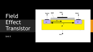
- 2. FET • The field-effect transistor (FET) is a type of transistor that uses an electric field to control the flow of current in a semiconductor. • FETs are devices with three terminals: • source • gate and • Drain • The Field Effect Transistor, FET, is a three terminal active device that uses an electric field to control the current flow and it has a high input impedance which is useful in many circuits.
- 3. Types • There are two types of field-effect transistors, • The Junction Field-Effect Transistor (JFET) and • The “Metal-Oxide Semiconductor” Field-Effect Transistor (MOSFET) or Insulated-Gate Field-Effect Transistor (IGFET).
- 4. FET
- 5. n- Channel and p- Channel
- 6. Comparison
- 7. V-I or Transfer Characteristics
- 8. V-I or Drain Characteristics
- 10. Comparison between FET and BJT SL No FET BJT 1 Unipolar Device Bipolar Device 2 Voltage – Controlled Device Current – Controlled Device 3 High Input Resistance – Few M-ohms Low Input Resistance – Few K-ohms 4 TCR - Negative TCR - Positive 5 No – Minority carrier Storage effect – high switching Speeds and Cutoff frequencies Suffers Minority carrier Storage effect – Lower switching Speeds and Cutoff frequencies 6 Less Noisy More Noisy 7 Simpler to Fabricate Difficult to Fabricate 8 Immune to radiation – excellent signal chopper Susceptible to radiation – stability is disturbed 9 Lower Gain BW Higher Gain BW 10 Susceptible to overload – required spl handling during installation Does not require spl handling during installation
- 11. MOSFET MOSFET – Two Basic Types Depletion Type – D-MOSFET Enhancement Type – E-MOSFET Difference – Difference in Construction
- 12. D-MOSFET • Gate to Source Voltage - Negative
- 13. E-MOSFET • Positive Gate to Source Voltage
- 14. Drain & Transfer Characteristics of E-MOSFET
- 15. Uni Junction Transistor (UJT)
- 16. UJT Working 𝑉𝑃 = 𝜂𝑉𝐵𝐵 + 𝑉𝐷 𝑅 = 1000 𝜂𝑉𝐵𝐵
- 17. V-I Characteristics of UJT
- 18. Applications of UJT • Trigger Device for SCR’s and TRIACs • Non-Sinusoidal Oscillators • Saw-Tooth generators • Timing circuits
- 19. Relaxation Oscillator • An oscillator is a device that produces a waveform by its own, without any input. Though some dc voltage is applied for the device to work, it will not produce any waveform as input. • The UJT relaxation oscillator is called so because the timing interval is set up by the charging of a capacitor and the timing interval is ceased by the rapid discharge of the same capacitor. • In electronics a relaxation oscillator is a nonlinear electronic oscillator circuit that produces a nonsinusoidal repetitive output signal, such as a triangle wave or square wave.
- 20. • This waveform depends generally upon the charging and discharging time constants of a capacitor in the circuit.
- 21. Relaxation Oscillator - Construction Construction: • The emitter of UJT is connected with a resistor and capacitor. • The RC time constant determines the timings of the output waveform of the relaxation oscillator. • Both the bases are connected with a resistor each. • The dc voltage supply VBB is given.
- 22. Relaxation Oscillator - Working Working: • Initially, the voltage across the capacitor is zero. • The UJT is in OFF condition. The resistor R provides a path for the capacitor C to charge through the voltage applied. V=V0(1−e−t/RC) • The capacitor usually starts charging and continues to charge until the maximum voltage VBB. • But in this circuit, when the voltage across capacitor reaches a value, which enables the UJT to turn ON (the peak voltage) then the capacitor stops to charge and starts discharging through UJT. • Now, this discharging continues until the minimum voltage which turns the UJT OFF (the valley voltage). • This process continues and the voltage across the capacitor, when indicated on a graph, the following waveform is observed. Relaxation oscillators are widely used in function generators, electronic beepers, SMPS, inverters, blinkers, and voltage controlled oscillators