Industrial Design Drafting Guide
•
32 gostaram•28,874 visualizações

The document discusses key concepts for part and assembly drawings including understanding the assembly, appropriate views and details, part identification, bills of materials, and title blocks. It also outlines steps for creating detail drawings using dimensions, tolerances, surface treatments, and ensuring final understanding. The U2 methodology provides a framework for remembering the important elements of technical drawings.

Recomendados
Mais conteúdo relacionado
Mais procurados
Mais procurados (20)
Semelhante a Industrial Design Drafting Guide
Semelhante a Industrial Design Drafting Guide (20)
Último
Último (20)
Industrial Design Drafting Guide
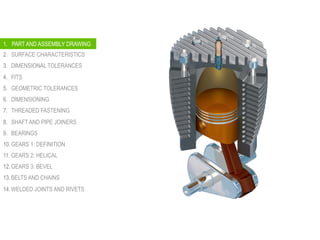
- 1. 1. PART AND ASSEMBLY DRAWINGS 2. SURFACE CHARACTERISTICS 3. DIMENSIONAL TOLERANCES 4. FITS 5. GEOMETRIC TOLERANCES 6. DIMENSIONING 7. THREADED FASTENING 8. SHAFT AND PIPE JOINERS 9. BEARINGS 10. GEARS 1: DEFINITION 11. GEARS 2: HELICAL 12. GEARS 3: BEVEL 13. BELTS AND CHAINS 14. WELDED JOINTS AND RIVETS 1. PART AND ASSEMBLY DRAWING
- 2. PART AND ASSEMBLY DRAWING Industrial Design 2015 Ramón Rubio CONCEPT | U2 METHODOLOGY An assembly drawing shows the assembled machine or structures, with all detail parts in their functional positions or as an exploded view where you can relate the parts to their functional positions.
- 3. PART AND ASSEMBLY DRAWING Industrial Design 2015 Ramón Rubio CONCEPT | U2 METHODOLOGY Assembly drawings created in 3D CAD for using 2D methods show how multiple parts fit together. They describe the end result – how the individual pieces, that must fit together, work.
- 4. PART AND ASSEMBLY DRAWING Industrial Design 2015 Ramón Rubio CONCEPT | U2 METHODOLOGY A part drawing is…detailed information: Drawings of the individual parts are called piece part drawings, part drawings or detail drawings. Detail drawings contain all of the necessary information to manufacture any specific part of a product.
- 5. PART AND ASSEMBLY DRAWING Industrial Design 2015 Ramón Rubio CONCEPT | U2 METHODOLOGY The information includes: • All necessary drawing views to fully define the shape • Dimensions • Tolerances • Material • Any specific notes: painting, coating, hardness, surface finishes, surface roughness, etc.
- 6. PART AND ASSEMBLY DRAWING CONCEPT | U2 METHODOLOGY Industrial Drafting 2015 Ramón Rubio ASSEMBLIES PARTS U2 (UNDERSTAND-UNDERSTAND) METHODOLOGY 1. UNDERSTAND 2. SCALE 3. VIEWS 4. DETAILS 5. IDENTIFICATION 6. BILL OF MATERIALS 7. TITLE BLOCK 8. UNDERSTAND 1. UNDERSTAND 2. SCALE 3. VIEWS 4. DIMENSIONS 5. TOLERANCES 6. SURFACE TREATM. 7. TITLE BLOCK 8. UNDERSTAND Allows you to remember the most important things in technical drawings (both: assemblies and part drawings)
- 7. PART AND ASSEMBLY DRAWING CONCEPT | U2 METHODOLOGY Industrial Drafting 2015 Ramón Rubio U2Remember! It’s a very important point!
- 8. PART AND ASSEMBLY DRAWING CONCEPT | U2 METHODOLOGY Industrial Drafting 2015 Ramón Rubio ASSEMBLIES 1. UNDERSTAND 2. SCALE 3. VIEWS 4. DETAILS 5. IDENTIFICATION 6. BILL OF MATERIALS 7. TITLE BLOCK 8. UNDERSTAND
- 9. PART AND ASSEMBLY DRAWING CONCEPT | U2 METHODOLOGY Industrial Drafting 2015 Ramón Rubio 1. UNDERSTAND
- 11. PART AND ASSEMBLY DRAWING CONCEPT | U2 METHODOLOGY Industrial Drafting 2015 Ramón Rubio 1. UNDERSTAND Ok, we are going to face assemblies like this one. But the simple or complex drawings begin with the same step: Understand WHAT you HAVE TO DO and HOW the assembly WORKS.
- 12. PART AND ASSEMBLY DRAWING CONCEPT | U2 METHODOLOGY Industrial Drafting 2015 Ramón Rubio We will deal with big parts and very small ones… Scale 1:1 Scale 1:2 2. SCALE
- 13. PART AND ASSEMBLY DRAWING CONCEPT | U2 METHODOLOGY Industrial Drafting 2015 Ramón Rubio Scale 2:1 2. SCALE
- 14. PART AND ASSEMBLY DRAWING CONCEPT | U2 METHODOLOGY Industrial Drafting 2015 Ramón Rubio …it is NOT mandatory, but keep in mind these numbers: 1, 2 and 5 ENLARGEMENT SCALES REDUCTION SCALES NATURAL SCALE 2. SCALE
- 15. PART AND ASSEMBLY DRAWING CONCEPT | U2 METHODOLOGY Industrial Drafting 2015 Ramón Rubio 3. VIEWS Assembly drawings are not usually dimensioned except to show the relative positions or total dimensions.
- 16. PART AND ASSEMBLY DRAWING CONCEPT | U2 METHODOLOGY Industrial Drafting 2015 Ramón Rubio 3. VIEWS
- 17. PART AND ASSEMBLY DRAWING CONCEPT | U2 METHODOLOGY Industrial Drafting 2015 Ramón Rubio Dimension: Only functional details and total measures 3. VIEWS
- 18. PART AND ASSEMBLY DRAWING CONCEPT | U2 METHODOLOGY Industrial Drafting 2015 Ramón Rubio 3. VIEWS Keep the purpose in mind when you select the views from an assembly drawing. The assembly drawing shows how the parts fit together and suggests the function of the entire unit. A complete set of orthographic views is not required.
- 19. PART AND ASSEMBLY DRAWING CONCEPT | U2 METHODOLOGY Industrial Drafting 2015 Ramón Rubio Because assemblies often have parts fitting into or overlapping other parts, 2D and 3D sections are useful views. In assembly sections it is necessary not only to show the cut surfaces but also to distinguish between adjacent parts. 3. VIEWS
- 20. PART AND ASSEMBLY DRAWING CONCEPT | U2 METHODOLOGY Industrial Drafting 2015 Ramón Rubio 3. VIEWS Assembly sections: The section lines must be drawn in opposing directions
- 21. PART AND ASSEMBLY DRAWING CONCEPT | U2 METHODOLOGY Industrial Drafting 2015 Ramón Rubio 3. VIEWS The assembly drawing does not need to show how to make the parts, just how to put them together. The information for each individual part is shown on its detail drawing.
- 22. PART AND ASSEMBLY DRAWING CONCEPT | U2 METHODOLOGY Industrial Drafting 2015 Ramón Rubio Often solid objects, or parts that do not show required information, are sliced by the cutting plane. Leave these parts unsectioned, or “in the round”. These include bolts, nuts, shafts, keys, screws, pins, ball or roller bearings, gears, spokes, and ribs, among others 3. VIEWS
- 23. PART AND ASSEMBLY DRAWING CONCEPT | U2 METHODOLOGY Industrial Drafting 2015 Ramón Rubio 4. DETAILS Draw some details if you need them. They help us to understand the drawing.
- 24. PART AND ASSEMBLY DRAWING CONCEPT | U2 METHODOLOGY Industrial Drafting 2015 Ramón Rubio 5. IDENTIFICATION Every part in an assembly drawing must be labelled using a leader and properly numbered.
- 25. PART AND ASSEMBLY DRAWING CONCEPT | U2 METHODOLOGY Industrial Drafting 2015 Ramón Rubio 5. IDENTIFICATION In order to avoid a lot of indications that will make the drawing cluttered. We can indicate sub-assemblies, and then provide another assembly drawing to indicate the part of that sub-assembly
- 26. PART AND ASSEMBLY DRAWING CONCEPT | U2 METHODOLOGY Industrial Drafting 2015 Ramón Rubio 6. PARTS LIST / BILL OF MATERIALS (BOM) A parts list or bill of materials itemizes the parts of a structure shown in an assembly drawing. It includes : Quantity required, name, part identification number (PIN), material, etc.
- 27. PART AND ASSEMBLY DRAWING CONCEPT | U2 METHODOLOGY Industrial Drafting 2015 Ramón Rubio All paper sizes with the same TITLE BLOCK 7. TITLE BLOCK TITLE BLOCK TITLE BLOCK
- 28. PART AND ASSEMBLY DRAWING CONCEPT | U2 METHODOLOGY Industrial Drafting 2015 Ramón Rubio 7. TITLE BLOCK The title block is used to identify the drawing. It includes: Name, owner, title, scale, etc.
- 29. PART AND ASSEMBLY DRAWING CONCEPT | U2 METHODOLOGY Industrial Drafting 2015 Ramón Rubio 7. TITLE BLOCK According to ISO standards, its width is always 180 mm
- 30. PART AND ASSEMBLY DRAWING CONCEPT | U2 METHODOLOGY Industrial Drafting 2015 Ramón Rubio A0 is the origin of this kind of sheets… 7. TITLE BLOCK
- 31. PART AND ASSEMBLY DRAWING CONCEPT | U2 METHODOLOGY Industrial Drafting 2015 Ramón Rubio …you get all sizes by folding the original A0 sheet 7. TITLE BLOCK
- 32. PART AND ASSEMBLY DRAWING CONCEPT | U2 METHODOLOGY Industrial Drafting 2015 Ramón Rubio Rectangle (0,7) Margins Draw the limits of the drawing A3, A2, A1, A0 A4 7. TITLE BLOCK
- 33. PART AND ASSEMBLY DRAWING CONCEPT | U2 METHODOLOGY Industrial Drafting 2015 Ramón Rubio 7. TITLE BLOCK
- 34. PART AND ASSEMBLY DRAWING CONCEPT | U2 METHODOLOGY Industrial Drafting 2015 Ramón Rubio 7. TITLE BLOCK
- 35. PART AND ASSEMBLY DRAWING CONCEPT | U2 METHODOLOGY Industrial Drafting 2015 Ramón Rubio 8. UNDERSTAND Once you have finished. Pause. Understand what you have done. Try to solve the problem backwards.
- 36. PART AND ASSEMBLY DRAWING CONCEPT | U2 METHODOLOGY Industrial Drafting 2015 Ramón Rubio Well…this could be tricky….
- 37. PART AND ASSEMBLY DRAWING CONCEPT | U2 METHODOLOGY Industrial Drafting 2015 Ramón Rubio DETAIL 1. UNDERSTAND 2. SCALE 3. VIEWS 4. DIMENSIONS 5. TOLERANCES 6. SURFACE TREATM. 7. TITLE BLOCK 8. UNDERSTAND
- 38. PART AND ASSEMBLY DRAWING CONCEPT | U2 METHODOLOGY Industrial Drafting 2015 Ramón Rubio A B E F C D A - BE - FC - D 1. UNDERSTAND You are asked to draw the detail drawing of part number 7. Try to visualize it. Imagine it…understand how it works and its relationship to the other parts.
- 39. PART AND ASSEMBLY DRAWING CONCEPT | U2 METHODOLOGY Industrial Drafting 2015 Ramón Rubio 2. SCALE REMEMBER the SCALE!!!!!
- 40. PART AND ASSEMBLY DRAWING CONCEPT | U2 METHODOLOGY Industrial Drafting 2015 Ramón Rubio 3. VIEWS
- 41. PART AND ASSEMBLY DRAWING CONCEPT | U2 METHODOLOGY Industrial Drafting 2015 Ramón Rubio 3. VIEWS
- 42. PART AND ASSEMBLY DRAWING CONCEPT | U2 METHODOLOGY Industrial Drafting 2015 Ramón Rubio detalle X(4:1) X 3. VIEWS
- 43. PART AND ASSEMBLY DRAWING CONCEPT | U2 METHODOLOGY Industrial Drafting 2015 Ramón Rubio 1x45º72 Tr12x3 10 Ø5 109 1x45º 57 1x45º Ø20 8 17 Ø2 detalle X(4:1) X Ø8 4. DIMENSIONS
- 44. PART AND ASSEMBLY DRAWING CONCEPT | U2 METHODOLOGY Industrial Drafting 2015 Ramón Rubio 1x45º72 Tr12x3 10 Ø5H9 109 1x45º 57 1x45º Ø20 8 17 Ø2F9 detalle X(4:1) X Ø8f8 5. TOLERANCES
- 45. PART AND ASSEMBLY DRAWING CONCEPT | U2 METHODOLOGY Industrial Drafting 2015 Ramón Rubio 1x45º72 Tr12x3 10 Ø5H9 109 1x45º 57 1x45º Ø20 8 17 Ø2F9 detalle X(4:1) X Ø8f8 N5N7N9 N5 N7 N5 6. SURFACE TREATMENT
- 46. PART AND ASSEMBLY DRAWING CONCEPT | U2 METHODOLOGY Industrial Drafting 2015 Ramón Rubio 7. TITLE BLOCK
- 47. PART AND ASSEMBLY DRAWING CONCEPT | U2 METHODOLOGY Industrial Drafting 2015 Ramón Rubio 8. UNDERSTAND
- 48. 1. PART AND ASSEMBLY DRAWINGS 2. SURFACE CHARACTERISTICS 3. DIMENSIONAL TOLERANCES 4. FITS 5. GEOMETRIC TOLERANCES 6. DIMENSIONING 7. THREADED FASTENING 8. SHAFT AND PIPE JOINERS 9. BEARINGS 10. GEARS 1: DEFINITION 11. GEARS 2: HELICAL 12. GEARS 3: BEVEL 13. BELTS AND CHAINS 14. WELDED JOINTS AND RIVETS 1. PART AND ASSEMBLY DRAWING
Notas do Editor
- An assembly drawing shows the assembled machine or structures, with all detail parts in their functional positions or as an exploded view where you can relate the parts to their functional positions.
- Assembly drawings created in 3D CAD or using 2D methods show how multiple fit together. They describe the end result – how the individual pieces that must fit together to work.
- Drawings of the individual parts are called piece part drawing, part drawings or detail drawings. Detail drawings contain all of the necessary information to manufacture any specific part being created for a product or design.
- The scale indicatess the ration of the size of the drawn object to its actual size. Expansion or enlargement scales are. 2:1, 4:1…
- Keep the purpose in mind when you select the views from an assembly drawing. The assembly drawing shows how the parts fit together and suggests the function of the entire unit. A complete set of orthrographic views is not required. The assembly drawing does not need to show how to make the parts, just how to put them together. The information for each individual part is shown on its detail drawing. -- Assembly drawings are not usually dimensioned except to show the relative positions or total dimensions.
- Because assemblies often have parts fitting into or overlapping other parts, 2D and 3D sections are useful views. In assembly sections it is necessary no only to show the cut surfaces but also to distinguish between adjacent parts.
- Because assemblies often have parts fitting into or overlapping other parts, 2D and 3D sections are useful views. In assembly sections it is necessary no only to show the cut surfaces but also to distinguish between adjacent parts.
- In assembly sections it is necessary no tonly show the cut surfaces but also to distinguish between adjacent parts. The section lines must drawn in opposing directions
- In assembly sections it is necessary no tonly show the cut surfaces but also to distinguish between adjacent parts. The section lines must drawn in opposing directions
- Often solid objects, or parts that do no show required infromation, are sliced by the cutting plane. Leave these parts unsectioned, or “in the round”. These includes bots, nuts, shafts, keys, screws, pins, ball or roller bearings, gear teeth, spokes, and ribs, among others
- Circled numbers called ballon numbers or ball tags are used to identify the parts in an assembly.
- A parts list or bill of materials itemizes the parts of a structure shown on an assembly drawing. The title block is enough on detail drawings of only one part, but a parts list is necessary on assembly drawings. It includes : quantity required, name, part identification number (PIN), material….
- A parts list or bill of materials itemizes the parts of a structure shown on an assembly drawing. The title block is enough on detail drawings of only one part, but a parts list is necessary on assembly drawings. It includes : quantity required, name, part identification number (PIN), material….
- Simplifying drawings: Drawing time is a considerable part of the total cost of a product. It makes sense to reduce drawing costs by using
- Understanding the vise
- Understanding the vise