SlideShare uma empresa Scribd logo
1 de 290
Dr/ ABD ALLAH NAZEER.MD.
Radiological imaging of fractures.
The skull is formed by the fusion of several flat bones held together by the
cranial sutures. Each of the flat bones consists of a thick outer table, the spongy
diploe, and a thinner inner table. The inner table is lined by a thick, fibrous,
adherent dura mater. A shallow subdural space lies between the inner surface
of the dura and the thin arachnoid mater that covers the surface of the brain.
Diagram of the cranium shows the anatomic layers.
Diagram of the skull vault shows the location
of various collections of fluid and/or blood.
Skull Radiographic Anatomy.
Lateral ViewPA skull View.
A skull fracture is a break in one or more of the eight bones that form
the cranial portion of the skull, usually occurring as a result of blunt
force trauma. If the force of the impact is excessive, the bone may
fracture at or near the site of the impact and cause damage to the
underlying physical structures contained within the skull such as
the membranes, blood vessels, and brain.
There are four major types of skull fractures:
Linear
Depressed
Diastatic
Basilar
Linear fractures are the most common, and usually require no
intervention for the fracture itself. Depressed fractures are
usually comminuted, with broken portions of bone displaced inward—
and may require surgical intervention to repair underlying tissue
damage. Diastatic fractures widen the sutures of the skull and usually
affect children under three. Basilar fractures are in the bones at the
base of the skull.
Linear skull fractures are breaks in the bone that transverse the full
thickness of the skull from the outer to inner table. They are usually fairly
straight with no bone displacement. The common cause of injury is blunt force
trauma where the impact energy transferred over a wide area of the skull.
Lateral skull radiograph in a child shows a long, linear fracture extending from the midline
in the occipital region across the occipital bone into the temporal bone.
Skull radiograph in a man shows a
linear temporoparietal fracture.
Lateral skull radiograph in a child
shows a long, linear fracture
running across the occipital bone.
Linear skull fracture in the simple X-ray and 3 dimensional computed tomography.
Linear skull fractures on the occipital bone (A and B) and parietal bone (C) show
not in the simple X-ray but clearly in the 3 dimensional computed tomography.
Linear fractures.
A depressed skull fracture is a type of fracture usually resulting from
blunt force trauma, such as getting struck with a hammer, rock or getting
kicked in the head. These types of fractures—which occur in 11% of severe
head injuries—are comminuted fractures in which broken bones displace
inward. Depressed skull fractures present a high risk of increased pressure
on the brain, or a hemorrhage to the brain that crushes the delicate tissue.
Plain radiographs of the head of a 25–year-old man who was assaulted with
a baseball bat show a curvilinear shadow indicating a depressed fracture.
Depressed skull fractures.
Depressed skull fracture in the simple X-ray and 3 dimensional computed tomography. A : Depressed
skull fracture on the parietal bone shows clearly both in the simple X-ray and 3 dimensional
computed tomography. B and C : Depressed skull fracture on the outer table of the parietal bone
shows not in the simple X-ray but clearly in the 3 dimensional computed tomography.
Axial brain and bone-window computed tomography scans show multiple fractures involving the
right temporal and parietal bones, with depression of several bone fragments into the brain
around which contusional hemorrhage is present. Also present are soft-tissue swelling, air in the
cranial cavity related to the bone fragments, and air in the subarachnoid space.
Massive bifrontal infarction following massive depressed fracture overlying the superior sagittal sinus
Diastatic fractures occur when the fracture line transverses one or more sutures of
the skull causing a widening of the suture. While this type of fracture is usually seen in
infants and young children as the sutures are not yet fused it can also occur in adults.
When a diastatic fracture occurs in adults it usually affects the lambdoidal suture as
this suture does not fully fuse in adults until about the age of 60.
Postmortem radiograph in a child with multiple
fractures due to non-accidental trauma show a
diastatic fracture of the sagittal suture.
Diastatic skull fractures in the simple X-ray and 3 dimensional computed tomography. A and
B : Diastatic skull fractures on the lambdoid, temporo-parietal and occipito-mastoid sutures
show clearly both in the simple X-ray and 3 dimensional computed tomography. C and D :
Diastatic skull fractures on the coronal, lambdoid, and temporo-parietal sutures show not in
the simple X-ray but clearly in the 3 dimensional computed tomography. Arrows.
Top view from a shaded-surface display, in a different patient, shows a
comminuted left temporofrontal fracture and diastasis of the metopic suture.
Basilar skull fractures are linear fractures that occur in the floor of
the cranial vault (skull base), which require more force to cause than
other areas of the neurocranium. Thus they are rare, occurring as
the only fracture in only 4% of severe head injury patients
Axial computed tomography image demonstrating skull base fracture
(arrow) through the petrous portion of the temporal bone.
Basilar fracture
A growing skull fracture (GSF) also known as a craniocerebral erosion or
leptomeningeal cyst due to the usual development of a cystic mass filled with
cerebrospinal fluid is a rare complication of head injury usually associated with
linear skull fractures of the parietal bone in children under 3. It has been reported
in older children in atypical regions of the skull such as the basiooccipital and the
base of the skull base and in association with other types of skull fractures. It is
characterized by a diastatic enlargement of the fracture.
Growing skull fracture or leptomeningeal cyst.
CT scan brain showing growing skull fracture with underlying
porencephalic cyst (a) before and (b) after repair Growing skull fracture.
CT and MR images of the patient’s growing fracture.
A cranial burst skull fracture usually occurring with severe injuries in infants
less than 1 year of age is a closed, diastatic skull fracture with cerebral extrusion
beyond the outer table of the skull under the intact scalp.
Cranial burst skull fracture.
A, Axial CT scan 3 hours after injury shows diastatic fracture with everted fracture edge and marked scalp
swelling. Underlying subdural and subarachnoid hemorrhage and small cortical contusion are present. B,
Coronal T2-weighted (3500/108/1) MR image 36 hours after injury reveals extent of cerebral herniation and
dural defect. Note high signal intensity of both intracranial and extra-cranial brain tissue.
A compound elevated skull fracture is a rare type of skull fracture where the
fractured bone is elevated above the intact outer table of the skull. This type of skull
fracture is always compound in nature. It can be caused during an assault with a
weapon where the initial blow penetrates the skull and the underlying meninges and,
on withdrawal, the weapon lifts the fractured portion of the skull outward. It can also
be caused the skull rotating while being struck in a case of blunt force trauma, the
skull rotating while striking an inanimate object as in a fall, or it may occur during
transfer of a patient after an initial compound head injury.
(a-c) Axial CT plain images bone
window showing the elevated skull
fracture of frontal bone with few
displaced fracture fragments and
pneumocephalus. Axial CT scan
plain images brain window (d-f)
showing parafalcine hemorrhage,
hemorrhagic, and nonhemorrhagic
contusions in frontal lobe,
extracalvarial herniation of the
brain parenchyma, and air pockets.
Preoperative clinical photograph (a) and CT head (b,c,d) showing degloving scalp wound, avulsed bone flap and exposed dura
Compound "elevated" fracture of the cranium.
Compound fracture of the cranium with brain injury.
Axial CT, shows “egg shell” type of skull fractures.
(a) Brain CT scan revealing a large depressed fracture over left frontal region; (b) Brain CT
scan with bone window to confirmed a large depressed fracture over left frontal region.
Axial bone CT scan showing an occipital depressed skull fracture and
penetration of left frontal and occipital region by the lion canines (arrow).
Facial fractures are commonly caused by blunt or penetrating
trauma sustained during motor vehicle accidents, assaults, and falls.
The facial bones are thin and light making them susceptible to injury.
Types
complex fractures which involve multiple facial buttresses:
naso-orbito-ethmoid (NOE) complex fracture
Le Fort fractures
zygomaticomaxillary complex fracture
Complex mid-facial fracture
fractures which involve a single facial buttress:
frontal sinus fracture
nasal bone fracture
orbital blow-out fracture
isolated zygomatic arch fractures
paranasal sinus fractures
alveolar process fractures
mandibular fracture
Facial Anatomy
Three-dimensional CT images of an adult skull in frontal (a) and lateral oblique (b) orientations with color
overlays show the superficial aspects of the horizontal and vertical facial buttresses and, in b, the sites of
potential complications of fractures involving each buttress. The horizontal buttresses are the upper transverse
maxillary (yellow), lower transverse maxillary (green), upper transverse mandibular (orange), and lower
transverse mandibular (purple) buttresses. The vertical buttresses are the medial maxillary (red), lateral
maxillary (blue), posterior maxillary (magenta), and posterior vertical mandibular (purple) buttresses.
System of facial partitions. Three-dimensional CT image of an adult skull with color overlays
shows partition of the facial anatomy into upper (red), middle (blue), and lower (yellow) thirds,
the system used by otolaryngologists to describe locations of fracture in the facial anatomy.
Complex Fractures Involving Multiple Facial Buttresses.
Le Fort fractures are complex facial fractures that result
from a high-force impact on the midface structures and
are characterized by a variable degree of craniofacial
dissociation spanning multiple facial buttresses. These
fractures were first described in the early 20th century by
French surgeon René Le Fort, who conducted experiments
in which blunt force was applied to the midface of
cadavers.
Le Fort fractures. Three-dimensional CT images of an
adult skull in frontal (a) and lateral (b) orientations with
color overlays show the osseous facial structures that are
typically affected by type I (red), type II (blue), and type III
(yellow) Le Fort fractures.
A type I Le Fort fracture, also known as a Guérin fracture or “floating palate,” results
in separation of the hard palate (lower transverse maxillary buttress) from the
remainder of the face and the skull base. This fracture pattern is horizontally oriented
and spans the anterior, lateral, and medial maxillary walls, transecting the inferior
margin of the pyriform aperture and nasal septum and extending posteriorly through
the pterygoid plates. Because the fracture extends antero-posteriorly in the axial
plane, it is typically best depicted on coronal and three-dimensional images.
(a) Axial unenhanced CT image at an inferior level of the maxillary
sinuses demonstrates bilateral fractures through the pterygoid
plates (arrowheads) and maxillary sinus walls (red arrows),
findings indicative of type I Le Fort fractures. Pterygomaxillary
dissociation due to fracture extension through the pterygoid plate
is a criterion for Le Fort classification. (b) Axial unenhanced CT
image at a superior level of the maxillary sinuses depicts fractures
through the medial margins of the anterior and posterior maxillary
walls, which are characteristic of type II Le Fort fractures (blue
arrows), and nondisplaced fractures through the zygomatic arch,
which are a component of type III Le Fort fractures (yellow
arrows). (c) Axial unenhanced CT image at the level of the orbits
shows fractures through the nasal bridge, medial orbital walls, and
lateral orbital walls (yellow arrows), findings indicative of type III
Le Fort fractures. (d) Coronal unenhanced CT image demonstrates
type I Le Fort fractures of the inferior aspect of the maxillary sinus
walls (red arrows), type II Le Fort fractures of the inferomedial
orbital walls (blue arrows), and type III Le Fort fractures of the
medial and lateral orbital walls (yellow arrows). (e) Three-
dimensional CT image in frontal orientation delineates type I (red),
II (blue), and III (yellow) Le Fort fractures.
(a) Three-dimensional CT image of facial bones demonstrates bilateral type I (red arrows)
and type II (blue arrows) and left-sided type III (yellow arrows) Le Fort fractures. (b) Three-
dimensional CT image obtained after internal fixation of the fractures shows plates and
screws spanning the medial maxillary (red arrows), lateral maxillary (blue arrows), right
lower transverse maxillary (green arrows), and right upper transverse maxillary (yellow
arrow) buttresses. Maxillomandibular fixation devices also are seen (purple arrows).
Three-dimensional CT image of the left medial maxillary buttress in lateral oblique orientation
shows a single fracture fragment that includes the lacrimal fossa at the expected insertion site
of the medial canthal tendon, findings indicative of a type I NOE fracture. Fractures through
the left frontal calvaria, lateral orbital rim, and zygomatic arch also are seen.
(a–c) Axial unenhanced CT images of the left orbital region
show nondisplaced fractures through the left
zygomaticofrontal (green arrow in a), zygomaticosphenoid
(yellow arrow in b), zygomaticomaxillary (blue arrow in c),
and zygomaticotemporal (red arrow in c) sutures. (d) Three-
dimensional CT image of the upper left facial region shows
a nondisplaced left zygomaticomaxillary complex fracture
through the zygomaticofrontal (green arrow),
zygomaticosphenoid (yellow arrow), zygomaticomaxillary
(blue arrow), and zygomaticotemporal (red arrow) sutures.
(a) Three-dimensional CT image of an adult face in oblique orientation depicts a right
zygomaticomaxillary complex fracture with a nondisplaced zygomaticofrontal suture (green arrow),
mildly displaced zygomaticomaxillary suture (blue arrow), and comminuted and displaced zygomatic
arch extending through the zygomaticotemporal suture (red arrow); the zygomaticosphenoid suture
was involved but is not depicted. A nondisplaced fracture of the base of the right coronoid process
(arrowhead) also is seen. (b) Three-dimensional CT image in the same orientation demonstrates
fixation of the zygomaticomaxillary and zygomaticotemporal sutures with plates and screws.
Frontal sinus fracture. Axial unenhanced CT image of the frontal bone demonstrates a
mildly displaced fracture of the anterior and posterior walls of the right frontal sinus with
associated opacification of the right frontal sinus and small foci of pneumocephalus.
Nasal bone fractures. (a) Axial unenhanced CT image shows a nondisplaced type 1 fracture
through the right nasal bone. Chronic dehiscence of the left orbital plate of ethmoid bone
is incidentally seen. (b) Axial unenhanced CT image depicts mildly comminuted and
displaced type 2 fractures through the bilateral nasal bones and nasal septum.
Zygomatic arch fracture. Axial unenhanced CT image demonstrates a comminuted
and depressed fracture of the left zygomatic arch with resultant compression of
the underlying temporalis muscle, a condition that could lead to trismus.
Fracture of the maxillary alveolar process. Axial unenhanced CT image depicts a fracture of the
maxillary alveolar process, with resultant avulsion of the medial and right lateral maxillary incisors.
Orbital blowout fracture. Coronal unenhanced CT image shows a displaced blowout
fracture of the left inferior orbital wall with resultant entrapment of the inferior rectus
muscle (arrow), which appears rounded in comparison with the normal right inferior
rectus muscle. The fracture extends through the inferior orbital canal (arrowhead).
Orbital blowout fracture before and after
fixation. (a) Coronal unenhanced CT image
demonstrates a left inferior orbital blowout fracture
with herniation of intraorbital fat and the inferior
rectus muscle. (b) Coronal unenhanced CT image
obtained after surgical fixation depicts metallic
surgical mesh placed along the inferior orbital wall
fracture. The position and appearance of the left
inferior rectus muscle are normal. (c) Axial contrast-
enhanced CT image obtained at follow-up shows
dilatation and rim like enhancement of the left
lacrimal duct (arrow), findings indicative of
dacryocystitis secondary to lacrimal duct obstruction,
a complication of either fracture or surgical fixation.
Orbital roof fracture. Coronal unenhanced CT image demonstrates mild inferior
displacement of a right orbital roof fracture with an adjacent extraconal hemorrhage.
Three-dimensional CT image with color overlays shows the parts of the mandible in
lateral orientation: the alveolar process (magenta), parasymphyseal region (blue), body
(red), angle (green), ramus (yellow), coronoid process (orange), and condyle (purple).
Axial unenhanced CT image of the mandible demonstrates a displaced fracture of the right
mandibular angle with distraction of the mandibular canal (yellow arrow). (b, c) Axial (b) and
three-dimensional (c) unenhanced CT images of the mandible after internal fixation of the right
posterior aspect of the upper transverse mandibular buttress across the mandibular angle
fracture (green arrow in c) and maxillomandibular fixation shows reapproximation of the right
mandibular body fracture fragments and mandibular canal (yellow arrow in b).
Mandibular fractures before and after internal
fixation. (a) Axial unenhanced CT image of the
mandible demonstrates a displaced fracture of the
right mandibular angle with distraction of the
mandibular canal (yellow arrow). (b,) Axial (b) and
three-dimensional (c) unenhanced CT images of the
mandible after internal fixation of the right
posterior aspect of the upper transverse
mandibular buttress across the mandibular angle
fracture (green arrow in c) and maxillomandibular
fixation shows reapproximation of the right
mandibular body fracture fragments and
mandibular canal (yellow arrow in b).
Dental fracture as a complication of lower transverse maxillary buttress fracture. Sagittal
unenhanced CT image of the facial midline demonstrates a maxillary alveolar process
fracture that extends through the right medial maxillary incisor root (arrow).
CSF leakage as a complication of medial maxillary buttress fracture. Coronal
unenhanced CT image of the face depicts a comminuted fracture through the
cribriform plate (arrow), a condition that may lead to CSF rhinorrhea. Fractures
of the bilateral orbital roofs, which could cause dural tears, also are seen.
Sinus obstruction as a complication of fracture of the nasolacrimal canal (medial maxillary
buttress fracture). (a) Coronal unenhanced CT image demonstrates a blowout fracture of the left
medial orbital wall with fracture fragments obstructing the left frontal recess (arrowhead), a
condition that could lead to mucocele formation, which is not present in this case. (b) Axial
unenhanced CT image at the level of the maxillary sinuses shows a minimally displaced fracture
through the nasolacrimal canal (arrow), which could lead to disruption of the nasolacrimal duct.
Telecanthus and optic nerve injury as complications of medial maxillary buttress fracture.
Axial unenhanced CT image demonstrates a comminuted fracture of the NOE complex with
telecanthus and involvement of the bilateral lacrimal fossae (arrows), findings indicative of
a type III fracture of the NOE complex with medial canthal tendon avulsion. A fragment of
the fractured right medial orbital wall impinges on the right optic nerve (arrowhead).
Fractures through the lateral maxillary buttress also may extend to the superior
orbital fissure or orbital apex, potentially leading to superior orbital fissure
syndrome or orbital apex syndrome, respectively. The lateral canthal ligament
may be injured at the site of its attachment to the lateral orbital wall.
Involvement of the superior orbital fissure in a lateral maxillary buttress fracture. Axial
unenhanced CT image demonstrates a mildly comminuted and displaced fracture of the left lateral
orbital wall with extension to the superior orbital fissure (arrow). This finding, when combined
with palsy of cranial nerves III, IV, V1, and VI, is indicative of superior orbital fissure syndrome.
Complication of a posterior maxillary buttress fracture. Axial unenhanced CT image
depicts comminuted fractures of the right anterior and posterior maxillary sinus
walls and zygomatic arch. Extension of the fracture through the right foramen ovale
(arrow) is suggestive of possible injury to the indwelling cranial nerve V3.
Temporal Bone Anatomy and Fractures.
Normal anatomy of the temporal bone. Axial high-resolution (a–e) and coronal MPR (f) multidetector CT images of the temporal bone
show the external auditory canal (EAC), carotid canal (CC) and jugular bulb (JB), malleus (M), facial nerve (FN), cochlea (C), semicircular
canals (SCC), internal auditory canal (IAC), incus (I), vestibule (V), vestibular aqueduct (VA), and mastoid air cells (MAC).
Temporal bone fractures are usually a sequelae of blunt head injury, generally
from severe trauma. Associated intracranial injuries, such as extra-axial
haemorrhage, shear (or diffuse axonal) injury and brain contusion are common.
Early identification of temporal bone trauma is essential to managing the injury
and avoiding complications.
Classification: direction
Temporal bone fractures classically are described concerning the long axis of
the petrous bone, being classified as:
longitudinal fractures
transverse fractures
mixed fractures
Classification: otic capsule involvement
Other classifications have been proposed and are more clinically relevant.
Temporal bone fractures can be classified based on:
otic capsule sparing
otic capsule violating
Involvement of the otic capsule is a predictor of more serious complications including:
facial nerve paralysis (2-5x as likely)
CSF leak (4-8x as likely)
sensorineural hearing loss (7-25x as likely)
epidural haematoma and subarachnoid haemorrhage
Longitudinal fracture. Axial high-resolution multidetector
CT image of the temporal bone shows a longitudinal
fracture (arrows) that extends into the middle ear.
Transverse fracture. Axial high-resolution multidetector CT image of
the temporal bone shows a transverse fracture (arrows) involving
the semicircular canal, with opacification of the mastoid air cells.
Mixed fracture. Axial high-resolution multidetector CT image of the temporal bone shows a fracture with
transverse (arrows) and longitudinal (arrowhead) components, findings indicative of a mixed fracture.
(a) Axial high-resolution multidetector CT image of the temporal bone shows an
otic capsule–sparing fracture (arrows). (b) Axial high-resolution multidetector CT
image of the temporal bone shows an otic capsule–violating fracture (arrows).
External auditory canal. (a) Axial high-resolution multidetector CT image of the temporal
bone shows the external auditory canal (arrows), which is intact. (b) In a different
patient, axial multidetector CT image of the cervical spine shows a longitudinal fracture
(arrowhead) that extends into the external auditory canal (arrows).
Ossicles. (a) Axial high-resolution multidetector CT image of the temporal bone
shows the normal incudomalleal relationship (arrowheads). (b) In a different
patient, axial multidetector CT image of the cervical spine shows incudomalleal
dislocation (arrow) secondary to a transverse fracture (arrowheads).
The cochlea. (a) Axial high-resolution multidetector CT image of the temporal bone shows
a normal cochlea (arrow). (b) In a different patient, axial multidetector CT image of the
cervical spine shows a transverse fracture (arrowheads) that extends into the cochlea.
The vestibule. (a) Axial high-resolution multidetector CT image of the temporal bone shows
normal vestibule anatomy (arrow). (b) In a different patient, axial maxillofacial multidetector
CT image shows a transverse fracture (arrowheads) that extends into the vestibule.
The semicircular canals. (a) Axial high-resolution multidetector CT image of the
temporal bone shows an intact semicircular canal (arrowheads). (b) In a different
patient, axial high-resolution multidetector CT image of the temporal bone shows a
subtle fracture line (arrowheads) that extends into the posterior semicircular canal.
Cervical spine anatomy fractures.
A-P view. Lateral View. Odontoid peg view
Cervical spine fractures can occur secondary to exaggerated flexion or extension, or because of direct trauma or axial loading.
The four major mechanisms are flexion, extension, rotational and shearing, each associated with certain fracture patterns:
flexion: most common mechanism
anterior atlantoaxial subluxation
anterior subluxation (hyperflexion sprain)
anterior wedge fracture
clay-shoveler fracture
flexion teardrop fracture
bilateral facet dislocation
hyperflexion fracture-dislocation
lateral flexion
unilateral occipital condyle fracture
lateral mass C1 fracture
flexion-rotation
unilateral facet dislocation
rotatory atlantoaxial dislocation
extension
hangman fracture
extension teardrop fracture
posterior arch C1 fracture
posterior atlantoaxial subluxation
extension-rotation
articular pillar fracture
floating pillar
axial loading/compression
burst fracture (with axial loading)
Jefferson fracture
complex injuries
atlantooccipital dissociation (shearing)
occipital condyle fracture
odontoid process fracture
Jefferson fracture. The first image is the
odontoid view, which illustrates the
lateral displacement of C1. The second
image is a coronal reconstruction from
a CT, which confirms the findings from
the odontoid view. The last image is a
CT axial view, which clearly shows the
location of the fractures of C1.
Dens Fracture Type I
Type I Odontoid fracture: fracture in superior tip of the odontoid.
This type of fracture is potentially unstable. It is a relatively rare fracture
Type II Odontoid Fracture: fracture at base of odontoid. It is the
most common type of odontoid fracture. It is an unstable fracture.
Dens type III fracture. The first image is an odontoid view, which shows the fracture line extending
beyond the base of the dens. The second image is a CT that confirms the fracture in the body of C2.
Hangman's Fracture
Radiographic features: (best seen on lateral view)
1. Prevertebral soft tissue swelling.
2. Avulsion of anterior inferior corner of C2 associated with rupture of the anterior longitudinal ligament.
3. Anterior dislocation of the C2 vertebral body.
4. Bilateral C2 pars interarticularis fractures.
Flexion Teardrop Fracture
Radiographic features: (best seen on lateral view)
1. Prevertebral swelling associated with anterior longitudinal ligament tear.
2. Teardrop fragment from anterior vertebral body avulsion fracture.
3. Posterior vertebral body subluxation into the spinal canal.
4. Spinal cord compression from vertebral body displacement.
5. Fracture of the spinous process.
Flexion Teardrop Fracture.
Bilateral Facet Dislocation.
Radiographic features: (best seen on lateral view)
1. Complete anterior dislocation of affected vertebral body by half or more of the vertebral body AP diameter.
2. Disruption of the posterior ligament complex and the anterior longitudinal ligament.
3. "Bow tie" or " bat wing" appearance of the locked facets.
Bilateral interfacetal dislocation.
50% anteroposition C5C6 as a result of the
dislocation.
In unilateral dislocation the anteroposition
is usually only 25%.
Widened space between spinous processes
C5 and C6 due to ligament rupture.
Ruptured disc space.
Bilateral interfacetal dislocation with complete transsection of the cord.
Unilateral Facet Dislocation.
Radiographic features: (best seen on lateral or oblique views)
1. Anterior dislocation of affected vertebral body by less than half of the vertebral body AP diameter.
2. Discordant rotation above and below involved level.
3. Facet within intervertebral foramen on oblique view.
4. Widening of the disk space.
5. "Bow tie" or "bat wing" appearance of the overriding locked facets.
Unilateral interfacetal dislocation.
On the axial view the left facet joint is normal and the
configuration has similarities with the hamburger.
On the right side the classic 'inverted hamburger sign' is
seen.
MRI-findings are:
Spinal cord lesion, which can be described as contusion,
edema or non-hemorrhagic spinal cord injury.
Rupture of the spinous ligaments.
Rupture of the ligamentum flavum.
Rupture of the disc with migration of disc material on the
posterior side of C4 and even on the anterior side of C5.
Clay Shoveler's Fracture
Radiographic features: (best seen on lateral view)
1. Spinous process fracture on lateral view.
2. Ghost sign on AP view (i.e. double spinous process of C6 or C7 resulting from displaced fractured spinous process).
Wedge Fracture.
Radiographic features:
1. Buckled anterior cortex.
2. Loss of height of anterior vertebral body.
3. Anterosuperior fracture of vertebral body.
Burst Fracture
Thoraco-lumbar spine Anatomy and Fractures.
The Thoraco-Lumbar Injury Classification and Severity score (TLICS) is a classification
system for thoracolumbar spine injuries, designed to assist in clinical management.
Simple compression fracture.
Pitfalls in diagnosing a compression fracture are:
Congenital anomalies
Osteochondrosis with irregular endplates
Limbus vertebrae
Retropulsion of posterosuperior vertebral body fragment.
Burst fracture with posterior vertebral body fragment.
Translation – Rotation fracture.
Severe compression of the vertebral body. However the most important findings
are the horizontal fractures of the posterior elements.
Spinous process distraction fracture with disruption of the ligamentum
flavum and a partial disruption of the interspinous ligament.
Distraction injury + PLC disruption.
Burst Fracture with PLC injury: very subtle widening of right facet joint.
Bilateral facet joint dislocation with anterior vertebral translation, PLC: always disrupted in translation.
Unilateral facet joint dislocation with anterior vertebral translation, PLC: always disrupted in translation.
Shoulder Anatomy and fractures.
Anteroposterior (a), Grashey (b), and axillary (c) radiographs of the shoulder show normal glenohumeral alignment.
The proximal humerus is composed of an anatomic head (black line), greater tuberosity (white line in a and b), lesser
tuberosity (brown line), and surgical neck (brown shading in a and b). The joint capsule attaches at the anatomic neck
of the humeral head (arrows in b). The glenoid process of the lateral scapula is formed by the glenoid fossa (yellow
shading) and glenoid neck (blue lines). Superiorly, the base of the coracoid process (gold contourline) demarcates the
anatomic glenoid neck (black arrowheads in a and b) and surgical glenoid neck (white arrowheads in a and b).
(a) Axillary radiograph of the shoulder shows a fracture of the surgical neck (SN) and disruption of
the normally smooth contour of the articular surface (arrow). (b, c) Oblique sagittal CT images of
the shoulder obtained through the articular surface medially (b) and the proximal humerus more
laterally (c) help confirm a comminuted fracture of the anatomic head with three articular
fragments. The lesser tuberosity (LT) accompanies fragment 1, whereas fragment 2 contains the
greater tuberosity (GT). Fragment 3 is separated (albeit minimally) from both tuberosities.
Comminuted fracture that includes the surgical neck (SN), greater tuberosity (GT), and
lesser tuberosity (LT), as well as anteroinferior dislocation of the anatomic head (AH).
Bony Bankart and Hill-Sachs lesions in a 54-year-old man
with chronic anterior shoulder instability.
Small Hill-Sachs lesion in a 43-year-old man with recurrent dislocations
Posterior glenohumeral dislocation in a 40-year-old man with alcohol-related seizures
Unstable anterior glenoid rim fracture (Ideberg type Ia injury)
Fracture of the glenoid surgical
neck with SSSC disruption
AP of the shoulder shows fracture of the glenoid surgical
neck (arrows) with a concomitant fracture of the
midclavicular shaft (arrowheads), findings that represent
the most common configuration of floating shoulder.
Scapula fractures are uncommon injuries, representing ~3% of all shoulder fractures.
Classification
intra-articular glenoid fracture
type I: avulsion of anterior glenoid margin
type II: transverse or oblique fracture through glenoid fossa exiting inferiorly
type III: oblique fracture through glenoid fossa exiting superiorly and associated
with acromioclavicular joint injury
type IV: transverse fracture exiting through medial scapular border
type V: combination of type II and type IV
type VI: comminuted glenoid fracture
extra-articular glenoid fracture
type I: glenoid neck fracture without clavicular fracture
type II: glenoid neck fracture with clavicular fracture and acromioclavicular
dislocation
coracoid process fracture
type I: fracture proximal to the coracoclavicular ligament
type II: fracture distal to the coracoclavicular ligament
acromial fracture
type I: minimally displaced
type II: displaced but does not reduce subacromial space
type III: displaced and narrow the subacromial space
Acute displaced intraarticular fracture from glenoid
to inferior portion of neck (Ideberg type 2).
Coronal volume-rendered 3D CT image shows acute
comminuted and displaced fracture extending from glenoid
articular surface to base of coracoid process (Ideberg type 3)
Anteroposterior
radiograph shows
acute anterior shoulder
dislocation.
Sagittal volume-rendered 3D CT
image shows acute fracture and
anterior displacement of large
fracture fragment (arrow) from
anterior glenoid rim (Ideberg
type 1).
Axial T2-weighted fat-saturated image
shows acute displaced bony Bankart
fracture at anterior inferior glenoid
rim (long arrow) with associated bone
marrow edema at posterolateral head
(short arrow).
Axillary radiograph shows acute
fracture of coracoid process
with anterior displacement
of more than 1 cm (line).
Axial CT image shows acute displaced
coracoid fracture (black arrow) and deep
Hill-Sachs impaction fracture at
posterolateral humeral head (white
arrow) after anterior shoulder dislocation.
Anteroposterior radiograph shows displaced
scapular neck (black arrow) and ipsilateral
midshaft clavicle (long white arrow) fractures.
Multiple ipsilateral displaced rib fractures are
also present (short white arrows).
Sagittal volume-rendered 3D CT image shows
degree of scapular neck angulation and
translation to greater detail. Degree of
displacement and comminution of clavicle
fracture is also better shown.
Anteroposterior radiograph shows acute
scapular neck fracture (black arrow) and
Rockwood type III acromioclavicular
joint separation (white arrow).
Sagittal volume-rendered 3D CT
image shows degree of scapular
neck angulation in greater detail.
Clavicular fractures are common and account for 2.6-10% of all fractures.
They usually require minimal treatment, which relies on analgesia and a
collar-and-cuff. However, in some cases open reduction and internal fixation
is required.
Radiology reports should not only include whether or not a fracture is present
but also comment on:
Fracture
location of the fracture along the shaft
angulation and fracture end displacement (including direction)
comminution
degree of overlap (measurement is useful)
Associated findings and relevant negatives
acromioclavicular joint and sternoclavicular joint alignment
coracoclavicular distance
glenohumeral joint
Associated traumatic injuries
rib fractures
vertebral fractures
scapular fractures (floating shoulder)
pneumothorax
Type 1 clavicular fracture (middle third).
Type 2 clavicular fracture (lateral third).
Type 1 comminuted clavicular fracture with skin tenting.
Type 1 comminuted
clavicular fracture
Type 3 clavicular fracture (medial third).
Type 3 acromioclavicular (AC) dislocation.
Type 2 acromioclavicular (AC) dislocation.
Medial clavicular fracture without injury to the sternoclavicular (SC) joint.
Proximal humeral fractures are common upper extremity fractures,
particularly in older patients, and can result in significant disability.
Reporting checklist
In addition to reporting the presence of a fracture it is important to
assess and comment on a number of other features.
Fracture: it should be noted that in most instances a description of the
fracture rather than a specific classification is sufficient, but the
features required to classify the fracture should be included
location of fracture lines
displacement and angulation of each part (> 1cm and >45 degrees
respectively is particularly important in the Neer classification)
presence of involvement of the articular surface
Associated injuries:
shoulder dislocation
acromioclavicular dislocation
scapular fracture
clavicle fracture
distal radial fracture (especially Colles fracture).
Diaphyseal humerus fracture.
Elbow Anatomy and Fractures.
Normal elbow. Anterior humeral line and radiocapitellar
line on normal lateral radiograph. The anterior humeral
line is drawn along the anterior cortex of the distal
humeral shaft and should bisect the middle third of the
capitellum. The radiocapitellar line is parallel to the long
axis of the radial neck and should bisect the capitellum.
These were originally reported for evaluation of the
pediatric elbow and have not been validated in adults.
Elbow, fractures and dislocations. Elbow effusion
with associated fat-pad elevation in the setting of
radial head fracture. The anterior fat pad is elevated,
and its undersurface is convex, giving the "spinnaker
sail sign." The posterior fat pad is elevated out of the
deep olecranon fossa and is visible just above the
cortex of the distal humerus.
Normal anterior fat pad.
Positive fat pad sign
both anteriorly as
well as posteriorly.
Supracondylar fractures. In A the anterior
humeral line passes through the anterior
third of the capitellum and in B even
more anteriorly. Notice positive posterior
fat pad sign in both cases
Gartland type III fracture
Gartland III fracture with medial-lateral
cross pin technique. After reduction
there is inadequate correction of medial
collapse. After two months there is
malunion with cubitus varus deformity.
MR of lateral condyle fracture. Milch II and unstable elbow. T2 image with fat saturation
on the right shows cartilaginous fracture. Fracture-fragment surrounded by synovial fluid.
Lateral Condyle fractures.
Capitellum fracture. Avulsion of medial epicondyle.
On AP-view the avulsed medial epicondyle
projects over the trochlea. Lateral view shows
the fragment to be trapped within the joint.
Avulsion of the medial epicondyle. The
amount of soft tissue swelling on the medial
side suggests that the elbow was dislocated.
Subtle radial neck fracture seen only on AP-view.
Radial neck fracture with tilt. Normal olecranon ossification centers in a
patient with a tilted radial neck fracture.
Olecranon fractures.
Fracture with Posterior
elbow dislocation.
Radiocapitellar view. What appears to be an isolated fracture of
capitellum on anterio-posterior and true lateral view demonstrates
an associated fracture of coronoid on radiocapitellar view
Fracture of the shaft of the humerus. A and B, Anteroposterior and lateral radiographs
demonstrate a comminuted fracture of the distal third of the humerus with a large butterfly
fragment (arrows). The butterfly fragment is pulled medially and posteriorly, while the
distal fragment (arrowheads) is retracted proximally due to the pull by the deltoid muscle.
Fractures of distal humerus. A and B, Anteroposterior and
lateral radiographs of the elbow show a comminuted
transverse extra-articular metaphyseal fracture (type A)
(arrows) with medial and volar displacement of the distal
fragment. C and D, Transtrochlear fracture (partial
articular, type B) (arrows) with mild displacement. The
fracture extends from the trochlea to the lateral column
of the distal humerus. E and F, Complete articular
fracture (type C) with marked displacement. The fracture
lines extend to both medial and lateral columns (arrows)
of the distal humerus, as well as to the articular surface
of the elbow (arrowhead). Distinction between type B
and type C is based on the number of columns involved.
Fractures of the radial head and olecranon process. A, Lateral radiograph of the elbow demonstrates a classic posterior fat pad
sign (arrows) produced by posterior bulge of the extra synovial fat. In addition, there is an elevated anterior fat pad (white
arrowheads). The cause of the joint effusion is a radial head fracture (black arrowhead). B, The black arrowhead demonstrates
a nondisplaced fracture of the radial head. C, Lateral radiograph of the elbow shows a transverse fracture of the olecranon
process (black arrowhead), a posterior fat pad sign (arrows), and elevated anterior fat pad (white arrowheads).
Elbow dislocation and fracture of the coronoid process. Lateral radiograph of the
elbow demonstrates a posterior dislocation of the radius and ulna with respect
to the distal humerus. A coronoid process fracture is noted (arrowheads).
Monteggia fracture-dislocation. A, Lateral radiograph of the forearm
demonstrates dorsal dislocation of the radial head (black arrowheads), along with
an angulated comminuted fracture of the proximal third of the ulna (arrows). Soft
tissue gas indicates an open injury. This is a type II Monteggia fracture-
dislocation. B, Volumetric (3D) CT reformation reveals an impacted fracture of the
radial head (white arrowhead) along with the Monteggia fracture-dislocation.
Forearm fractures are a group of fractures that occur in the forearm following trauma.
The radius and ulna are bound together at the proximal and distal radioulnar joints and act
as a ring.
Radial or ulnar fracture will be visible on at least one view. It is important to determine
what type of fracture it is, e.g. transverse, oblique, comminuted.
If there is only one fracture, it is important to look for a second fracture, or see if there is
damage to the proximal or distal radioulnar joint:
Monteggia fracture-dislocation: radial fracture and dislocation of the radial head at the elbow
Galeazzi fracture-dislocation: radial fracture dislocation of the distal ulna from the carpus.
Galeazzi fracture-dislocations
Galeazzi fracture-dislocation. A and B, Lateral and anteroposterior radiographs of the forearm show a
displaced transverse fracture of the radial shaft at the junction of the middle and distal thirds, along with
dislocation of the distal radioulnar joint (DRUJ). Dislocation of the radius relative to the ulna on the lateral
radiograph and radial foreshortening (double-headed arrow) are clues suggesting DRUJ disruption.
Monteggia fracture-dislocations
Monteggia fracture-dislocation.
Combined Monteggia and Galeazzi fractures.
Wrist anatomy and fractures.
A Colles' fracture is a fracture of the distal metaphysis of the radius with
dorsal angulation and displacement leading to a 'silver fork deformity'.
Smith's fractures occur in younger patients and are the result of high
energy trauma on the volar flexed wrist.
Volar comminution and intraarticular extension are more common.
Volar-type Barton's is a fracture-dislocation
of the volar rim of the radius.
Dorsal-type Barton's is a fracture-
dislocation of the dorsal rim of the radius.
Die punch fracture.
Chauffeur's fracture
An isolated fracture of the radial styloid process is also called a Hutchinson's or chauffeur's fracture.
Ulnar styloid process fracture
An ulnar styloid process fracture is usually associated with radial fractures and rarely isolated.
Torus fractures, or buckle fractures, are extremely common injuries in children.
Because children have softer bones, one side of the bone may buckle.
The word torus is derived from the Latin word 'Tori' meaning swelling or protuberance.
These injuries tend to heal much more quickly than the similar greenstick fractures.
Green stick fracture
Epiphysiolysis fracture.
These are usually Salter Harris type II epiphysiolysis fractures.
Scaphoid fractures (i.e. fractures through the scaphoid bone) are common, in some instances
can be difficult to diagnose, and can result in significant functional impairment.
Fractures can occur essentially anywhere along the scaphoid, but distribution is not even 9:
Waist of scaphoid: 70-80%
Proximal pole: 20%
Distal pole (or so-called scaphoid tubercle): 10%
Scaphoid Fractures
Scaphoid Fractures
The lateral wrist projection image
demonstrates a convincing positive pronator
quadratus soft tissue sign and a complete
transverse fracture of the lunate
The PA wrist projection image
was largely unremarkable
(arguably some soft tissue signs)
Fracture of the Lunate
Triquetral fracture. There is a small avulsion from the dorsum of the triquetrum seen only
on the lateral projection (red arrow). The pisiform overlies the triquetrum in the AP and
oblique views and tends to obscure the fracture (white arrows).
A coronal T1-weighted image of the wrist showing a
radio-graphically occult capitate fracture (arrows).
Pelvic fractures can be simple or complex and can involve any part of
the bony pelvis. Pelvic fractures can be fatal, and an unstable pelvis
requires immediate management.
Classification
Four main forces have been described in high-energy blunt force trauma
that results in unstable pelvic fractures:
Anteroposterior compression: result in an open book or sprung pelvis
fractures
Lateral compression: result in a windswept pelvis
Vertical shear: results in Malgaigne fracture or bucket handle fracture
Combined mechanical: occur when two different force vectors are
involved and results in a complex fracture pattern
Isolated stable pelvic fractures can also occur in the context of lower
energy mechanisms or sporting injuries:
acetabular fracture
pubic ramus fracture
iliac wing fracture (Duverney fracture)
avulsion fractures (e.g. ASIS, iliac crest, ischial tuberosity)
Computer-generated lateral view of the pelvis shows
the three components of each of the paired innominate
bones: ilium (yellow), ischium (orange), and pubis
(green). The borders between the three bones are
determined by the location of the immature physeal
triradiate cartilage, which is fully fused by adulthood.
Computer-generated image shows the stabilizing
structures of the pelvic ring. The bony pelvic ring (blue
circle) is made up of the sacrum and bilateral innominate
bones and stabilized by the SI (1), sacrospinous (2), and
sacrotuberous (3) ligaments. Secondary stabilization is
provided by the iliolumbar ligaments (*).
Anatomy and Biomechanics of the Pelvis
Pelvic apophyseal avulsion fractures diagram
lateral compression type 1 lateral compression type 2
lateral compression type 3
Young and Burgess classification of
pelvic ring injury. Computer-generated
images show lateral compression type
1 (a), lateral compression type 2 (b),
lateral compression type 3 (c), AP
compression type 1 (d), AP compression
type 2 (e), AP compression type 3 (f),
and vertical shear (g) fractures.
Pelvic open book fracture
Malgaigne fracture.
Iliac crest avulsion.
Lateral compression type 1 injury in two patients.
Lateral compression type 2 injury in an 18-year-old
woman who was an unrestrained driver in a motor
vehicle accident. (a) Pelvic radiograph shows left-sided
overlapping superior and inferior pubic rami fractures
(white arrows) and widening of the left SI joint (black
arrow). (b) Axial CT image shows a fracture of the
anterior sacrum at the site of the anterior SI ligament
attachment (black arrow) and widening of the SI joint.
A crescent fracture (white arrow) involving the left iliac
bone is also seen. The posterior SI ligament is keeping
the fragment attached to the sacrum. (c) Coronal CT
image obtained at the level of the posterior SI joint
shows the crescent fracture (black arrow). No
craniocaudal displacement of the iliac bone (white
arrow) is seen, a finding that excludes vertical shear
injury.
Lateral compression type 3 injury
Vertical shear pelvic injury.
Combined lateral compression and vertical shear injury.
Acetabulum anatomy.
Anterior wall acetabular fracture. A computed tomography (CT)
scan demonstrates an oblique fracture through the anterior
wall of the left acetabulum (arrow). Such fractures are
uncommon in isolation. The patient had other pelvic injuries
Computed tomography (CT) scan of a posterior wall
acetabular fracture. The oblique fracture of the left
acetabulum is clearly depicted. The degree of
displacement and marginal impaction can be determined
more accurately with CT scanning than with radiography.
Both-column acetabular fracture. Anteroposterior pelvic radiograph (A), bilateral oblique pelvic radiographs
(B, C), axial CT scan (D), and sagittal reconstruction CT scan (E) show acetabular fracture (straight arrows, A-
C), with break in obturator ring (arrowheads, A-C) and extension into iliac wing (curved arrows). Note coronal
plane of fracture on CT and superior pubic ramus fractured at puboacetabular junction.
T-shaped acetabular fracture.
Anteroposterior pelvic radiograph (A),
bilateral oblique pelvic radiographs (B,
C), axial CT scan (D), and surface-
rendering 3D CT scan viewed laterally
(E), with right hemipelvis and femur
removed, show obturator ring fractures
(arrowheads) and transverse
component (arrows) through
acetabulum. Note characteristic
oblique-sagittal orientation of
transverse acetabular fracture
component on CT scans that is
transverse relative to acetabulum on
radiographs.
Transverse acetabular fracture.
Anteroposterior pelvic radiograph
(A), bilateral oblique pelvic
radiographs (B, C), axial CT scan
(D), and surface-rendering 3D CT
scan viewed laterally (E), with right
hemipelvis and femur removed,
show fracture (arrows) orientation
transverse to acetabulum,
disrupting iliopectineal and
ilioischial lines (arrowheads). Note
characteristic sagittal-oblique
fracture plane on CT scan (D).
Transverse with posterior wall
acetabular fracture.
Anteroposterior pelvic radiograph
(A), bilateral oblique pelvic
radiographs (B, C), axial CT scan
(D), and surface-rendering 3D CT
scan viewed laterally (E), with right
hemipelvis and femur removed,
show transverse fracture (straight
arrows) disrupting iliopectineal
and ilioischial lines (arrowheads)
with displaced and comminuted
posterior wall fracture fragment
(curved arrows).
Isolated posterior wall acetabular fracture. Anteroposterior pelvic radiograph (A), bilateral oblique
pelvic radiographs (B, C), axial CT images (D, E), and parasagittal reconstruction CT image (F) show
displaced fracture fragments (curved arrows) from isolated posterior wall fracture (straight arrow, D).
Transverse with posterior wall acetabular
fracture. An anteroposterior radiograph of the
pelvis shows that the central dislocation of
the left femoral head results in the disruption
of the iliopectineal and ilioischial lines. In
addition, the left posterior acetabular wall is
disrupted. left obturator oblique view of the
pelvis view better demonstrates the anterior
column and posterior wall disruption. (CT)
scan of a transverse fracture with a posterior
wall acetabular fracture
Both-column acetabular fracture, X-Ray and CT images.
There are several classification systems for sacral fractures, but the most commonly
employed are the Denis classification and subclassification systems, and the Isler
classification system. These classification systems are important to understand as proper
classification can impact management.
Denis classification
zone 1: fracture involves the sacral ala lateral to the neural foramina
zone 2: fracture involves the neural foramina, but does not involve the spinal canal
zone 3: fracture is medial to the neural foramen, involving the spinal canal; these may be
transverse or longitudinal, and can be sub-classified into 4 types:
type 1: only kyphotic angulation at the fracture site (no translation)
type 2: kyphotic angulation with anterior translation of the distal sacrum
type 3: kyphotic angulation with complete offset of the fracture fragments
type 4: comminuted S1 segment, usually due to axial compression
Morphologic injury patterns of zone 3 fractures
“H” shaped fracture
“U” shaped fracture
“ʎ” shaped fracture (lambda)
“T” shaped fracture
Isler classification
Used for fractures that involve the lumbosacral articulation:
Isler 1: fracture occurs lateral to the L5/S1 facet
Isler 2: fractures line involves the L5/S1 facet
Isler 3: fracture line extends medially to the L5/S1 facet
U-shaped pelvis fracture.
(A) Sagittal initial CT scan shows type 1 upper sacral fracture with an anterior simple bending of the
upper sacrum fragment. (B) Simple initial lateral radiogram shows upper sacral non-displaced fracture.
(C) Simple radiologic image shows no differences between initial and 6 months follow up studies.
(A) Sagittal initial CT scan shows type 2 upper sacral fracture with a posterior displacement of
the upper fragment. (B) Simple initial lateral radiogram shows comminuted fractures with
displacement. (C) Simple radiologic image shows malunion at 4 months follow up studies.
(A) Sagittal preoperative CT scan shows type 2 upper sacral fracture with a posterior displacement of the
upper fragment. (B) Axial preoperative CT scan shows narrowing of sacral canal due to posterior translation
of bony fragment. (C) Axial CT scan after laminectomy at level S1-S2 shows elimination of posterior wall of
sacral canal. (D) Sagittal CT scan shows malunion of fracture site at 3 months follow up studies.
Initial computed tomography scan shows a
displaced comminuted sacral fracture with
narrowing of the sacral canal at the S1-S2 level.
(A) and axial T1-weighted magnetic resonance (B),
T2-weighted magnetic resonance (C) images
showing left S1 nerve root compression due to a
displaced S1 sacral body and hematoma.
Computed tomography scan with an isolated S5 fracture after a same-level fall.
Fractures of the coccyx are thought to be trivial injuries, however, they can take a
long while to heal. (Chronic coccyx pain is termed coccydynia). The coccyx is broken by
a direct blow, such as a fall on the buttocks. Another less common mechanism is by
pressure from the passage of the fetus down the birth canal during delivery.
Four examples of posterior luxation (dislocation of a joint, with the lower joint surface slipping backwards)
Low sacral fracture.
CT scan of broken sacrum and coccyx
Image showing edema around coccygeal segment.
Femoral Neck Anatomy and fractures.
Neck of femur fractures (NOF) are common injuries sustained
by older patients who are both more likely to have unsteadiness of
gait and reduced bone mineral density, predisposing to fracture.
Elderly osteoporotic women are at greatest risk.
Classification
Femoral neck fractures are a subset of proximal femoral fractures.
The femoral neck is the weakest part of the femur.
Since disruption of blood supply to the femoral head is dependent
on the type of fracture and causes significant morbidity, diagnosis
and classification of these fractures is important.
Neck of femur fractures are considered intracapsular fractures
(also called proximal femoral fractures). Intracapsular fractures
include:
Subcapital: femoral head/neck junction
Transcervical: midportion of femoral neck
Basicervical: base of femoral neck
Valgus- and varus-impacted subcapital fractures. (a)
Anteroposterior radiograph in an 88-year-old woman who had
sustained a fall demonstrates characteristic valgus angulation of
the proximal fracture fragment, a finding that is most evident
due to the presence of subtle cortical overlap of the lateral
femoral neck and head cortex forming a triangular opacity
(arrow). (b) Anteroposterior radiograph of the hip in a 66-year-
old woman who had sustained a fall shows a varus-impacted
fracture, which can be distinguished from the more common
valgus-impacted variant on the basis of the presence of a
triangular opacity representing medial cortical overlap (small
arrow), along with a displaced lateral cortical fracture (large
arrow). (c) Coronal CT image of the hip in a 68-year-old woman
shows a varus-impacted fracture with medial cortical overlap
(triangular opacity [small arrow]), as well as a prominent,
inferiorly projecting cortical rim, a finding that is often mistaken
for an osteophyte (mushroom cap deformity) (large arrow).
Osteoporosis and complaints of groin pain. (a) Initial anteroposterior radiograph demonstrates
focal disruption of the lateral femoral cortex (white arrow) with the fracture line oriented
perpendicular to the primary tensile trabeculae (black arrows). The patient was diagnosed with
an incomplete insufficiency-type stress fracture and was placed under strict activity restrictions.
(b) Follow-up anteroposterior radiograph obtained after acute atraumatic exacerbation of groin
pain demonstrates completion of the now-displaced femoral neck fracture (arrow).
Intertrochanteric fractures with various morphologic features in
women between ages 65 and 80 years. (a) Anteroposterior
radiograph shows a type 1 fracture, which is apparent only as a
nondisplaced fracture line extending through the lateral and
medial cortex (arrow). (b) Anteroposterior radiograph obtained
in a different patient shows a type 2 fracture that is moderately
displaced but still reflects a mechanically stable injury (arrow).
(c) Anteroposterior radiograph obtained in a third patient
shows a more severe type 5 fracture with comminution of both
the posteromedial (small arrow) and posterolateral (large
arrow) cortices, findings that indicate a highly unstable injury.
Sub-capital hip fracture. On the frontal view, there is a step-off in the cortex superiorly (red arrow)
while there is abnormal overlapping of the femoral head and neck (white arrows) due to impaction.
On the lateral view, the same step-off can be seen (red arrow) as well as the impaction (white arrow).
X-ray of fracture shaft femur.
Femur shaft fracture.
Knee anatomy and fractures.
Avulsion fractures of the knee are numerous due to the many ligaments and tendons
inserting around this joint. They include 1:
Anterior cruciate ligament avulsion fracture
Posterior cruciate ligament avulsion fracture
Avulsion of the medial collateral ligament
origin of MCL avulsion fracture: Stieda fracture
insertion of deep fibers: reverse Segond fracture
Avulsion fracture of the deep fibers
avulsion fracture of the insertion of superficial fibers of MCL: 5 cm below the joint line
Avulsion of the lateral collateral ligament:
origin of LCL: above popliteal groove
conjoined tendon: fibular head below the tip, biceps femoris and insertion of LCL avulsion
fracture
arcuate ligament complex avulsion fracture (arcuate sign)
Segond fracture
iliotibial band avulsion fracture: Gerdy tubercle
Semimembranosus tendon avulsion fracture
patellar fractures
quadriceps tendon avulsion fracture
patellar sleeve fractures
chronic injuries
Osgood-Schlatter disease
Sinding-Larsen-Johansson syndrome
Jumper's knee
Segond fracture is an avulsion fracture of the knee that involves the
lateral aspect of the tibial plateau and is very frequently (~75% of cases)
associated with disruption of the anterior cruciate ligament (ACL) tear.
Segond fracture.
Segond fracture and bony avulsion of ACL.
Segond fracture.
Tibial plateau fractures. Line drawings of Schatzker types I, II, and III tibial plateau fractures.
Tibial plateau fractures. Line drawings of Schatzker types IV, V, and VI tibial plateau fractures.
Tibial plateau fractures. Radiograph
of the knee shows lateral plateau
splitting, a Schatzker I injury. There is
no articular depression.
Tibial plateau fractures. A different patient illustrates a
Schatzker II injury with subtle lateral articular depression.
Tibial plateau fractures. Axial CT image of the same patient as in the previous image
shows the extent of the lateral tibial plateau fracture. In this case, it extends to the lateral
tibial margin and an associated fibular head fracture is seen. This is a Schatzker II injury.
Tibial plateau fractures. Radiograph of the knee reveals
fractures through both the medial and the lateral tibial
plateau along with a fibular head fracture and a fracture
through the tibial metaphysis. This is a Schatzker VI injury.
Tibial plateau fractures. Radiograph of the
knee shows a different Schatzker VI fracture.
Tibial plateau fractures. Axial and coronal reformatted CT image demonstrates the extensive
fractures of both the lateral and medial aspects of the tibial plateau, a Schatzker VI injury.
Tibial plateau fractures. Coronal reformatted CT. Initial narrow collimation axial CT data can be
reconstructed into sagittal and coronal planes. This technique is useful to evaluate for fracture lines
parallel to the axial imaging plane, degree of articular depression, and degree of diastasis between
major fracture fragments. The best reconstructions are made when the initial data set consists of axial
images of less than 2 mm thickness. In this particular case, an axial data set of 1 mm images was
reconstructed into this coronal image demonstrating fractures of the tibial spines.
AP image and lateral image (mediolateral projection) of an intercondylar eminence fracture.
AP image, lateral image (mediolateral projection) and axial image. The vertical
fracture is clearly visible on the axial image and subtly identifiable on the AP image.
Hoffa fracture of the medial femoral condyle sustained after being hit with a bat. AP ( a ) and lateral ( b ) knee
radiographs demonstrating a coronally oriented fracture ( arrow ) of the medial femoral condyle, and a
suprapatellar joint effusion ( arrowhead ). The fracture is not appreciated on the AP view. Sagittal ( c ) and shaded
Multiple femur fractures.
Basically there are three main types of ankle fractures.
Weber classified them as:
type A - infrasyndesmotic
type B - transsyndesmotic
type C - suprasyndesmotic
These fractures are identical to the fractures described by Lauge-Hansen as supination-
adduction, supination-exorotation and pronation-exorotation.
We will first give a short overview of these fractures and then discuss them in more
detail.
Weber A
Occurs below the syndesmosis, which is intact.
According to Lauge-Hansen, it is the result of an adduction force on the supinated foot.
Stage 1 - Tension on the lateral collateral ligaments results in rupture of the ligaments
or avulsion of the lateral malleolus below the syndesmosis.
Stage 2 - Oblique fracture of the medial malleolus.
Weber B
This is a transsyndesmotic fracture with usually partial - and less commonly, total - rupture
of the syndesmosis.
According to Lauge-Hansen, it is the result of an exorotation force on the supinated foot.
Stage 1 - Rupture of the anterior syndesmosis
Stage 2 - Oblique fracture of the fibula (this is the true Weber B fracture)
Stage 3 - Rupture of the posterior syndesmosis
or - fracture of the malleolus tertius
Stage 4 - Avulsion of the medial malleolus
or - rupture of the medial collateral bands
Weber C
This is a fracture above the level of the syndesmosis. Usually there is a total rupture of the
syndesmosis with instability of the ankle.
According to Lauge-Hansen, it is the result of an exorotation force on the pronated foot.
Stage 1 - Avulsion of the medial malleolus or - ligamentous rupture
Stage 2 - Rupture of the anterior syndesmosis
Stage 3 - Fibula fracture above the level of the syndesmosis (this is the true Weber C
fracture)
Stage 4 - Avulsion of the malleolus tertius or - rupture of the posterior syndesmosis
Weber and Lauge-Hansen summary
Weber A = Infrasyndesmotic
Avulsion of the lateral malleolus
Oblique fracture of the medial
malleolus (uncommon)
Weber B = Transsyndesmotic
Rupture of the anterior syndesmosis
Oblique fracture of the fibula
Rupture of the posterior syndesmosis
or - fracture of the malleolus tertius
Avulsion of the medial malleolus -
or - rupture of the medial bands
Weber C = Suprasyndesmotic
Avulsion of the medial malleolus
or - ligamentous rupture
Rupture of the anterior syndesmosis
Fibula fracture above the level of the
syndesmosis
Avulsion of the malleolus tertius
or - rupture of the posterior
syndesmosis
Weber A, stage 1
Weber type A fractures, stage 1.
Weber A - stage 2
Stage 1: Rupture of anterior tibiofibular
ligament - or avulsion fracture (Tilleaux)
Weber B - stage 3 and 4
Weber B fracture.
Weber C fracture - stage 3.
Weber C fracture - at least stage 3
Weber C fracture - stage 4
Trimalleolar Weber B fracture
The Salter-Harris classification describes fractures that involve the epiphyseal plate or
growth plate.
The most common is type II, which accounts for 75%.
Type I - transverse fracture through the growth plate or physis
Type II - fracture through the growth plate and the metaphysis, sparing the epiphysis
Type III - fracture through growth plate and epiphysis, sparing the metaphysis
Type IV - fracture through all three elements of the bone, the growth plate, metaphysis, and epiphysis
Type V - compression fracture of the growth plate
These Salter-Harris fractures can be easily missed.
In many cases there is only minimal or no displacement.
The fracture through the growth plate is usually obscure and difficult to differentiate from normal
variations of the growth plate. And finally we tend not to look carefully at the epiphysis.
Type I Salter-Harris fractures
Type 11 Salter-Harris fractures.
Type III is a fracture through the growth plate and epiphysis sparing the metaphysis.
Type IV
Triplane fracture
Tilleaux fracture
juvenile Tilleaux
Calcaneal fractures are the most common tarsal fracture, and can occur in
a variety of settings.
Calcaneal fractures can be divided broadly into two types depending on
whether there is articular involvement of the subtalar joint:
extra-articular: 25-30%
anterior calcaneal process fracture
calcaneal tuberosity avulsion fracture
extra-articular body fracture
lover's fracture
medial sustentaculum
intra-articular: 70-75%
intra-articular body fracture
The calcaneus is also a common site of stress fractures, occurring in the
posterosuperior aspect.
Another method of classification is as
Type A fractures: the anterior process of the calcaneus is fractured
type B: fracture of the mid calcaneus, trochlear process, and sustentaculum tali
Type C: fracture of the posterior tuberosity
Calcaneal fracture.
(a) Lateral radiograph shows a joint depression type fracture, with the fracture
line exiting at the inferior calcaneal surface (arrow). (b) Lateral radiograph shows
a tongue type fracture, with the fracture line exiting at the posterior calcaneal
surface (arrow). Note also the joint depression type fracture line (arrowhead).
(a) and axial (b) multidetector CT scans of the right foot show a severe
comminuted calcaneal fracture involving the lateral (*), central (arrow), and
medial (arrowhead) aspects relative to the posterior facet and subtalar joint.
Hawkins-Canale type I talar neck fracture. Sagittal reformatted CT image of the ankle
shows a nondisplaced fracture (arrow) through the talar neck. Note the inferior extension
of the fracture anterior to the posterior subtalar facet, defining the talar neck location.
Hawkins-Canale type II talar neck fracture. Lateral radiograph (a) and sagittal
reformatted CT image (b) of the ankle show a vertical fracture of the talar neck
(arrow in a) and dislocation of the posterior subtalar facet (arrowhead)
Hawkins-Canale type III talar neck fracture. (a) AP radiograph of the ankle shows subtalar and tibiotalar
dislocation and lateral extrusion of the talar body. (b) Lateral radiograph of the ankle shows the vertical
fracture line through the talar neck (arrow). Gas and edema in the soft tissues are consistent with open injury
(arrowhead). (c) Three-dimensional reconstructed CT image of the ankle (in another patient) shows a talar
neck fracture, tibiotalar and subtalar dislocation, and medial talar body extrusion.
Hawkins-Canale type IV talar neck fracture. (a) AP radiograph of the ankle shows tibiotalar and
subtalar dislocation with lateral extrusion of the talar body. Subtle offset at the talonavicular
joint is also seen (arrowhead). (b) Lateral radiograph of the ankle shows the vertical fracture
line through the talar neck (arrow) and malalignment at the talar head (arrowhead).
Talar dislocation. (a) Lateral radiograph of the ankle shows tibiotalar, talonavicular, and
talocalcaneal dislocations. The talus is rotated and extruded anteriorly and laterally. (b) AP
radiograph of the ankle shows disruption of the ankle mortise and lateral displacement of the talus.
CT images in the axial (A), coronal (B), and sagittal (C) planes demonstrate a chronic,
ununited navicular stress fracture complicated by osteonecrosis and fragmentation.
Navicular stress fracture (Sagittal).
Lisfranc Injury
Lisfranc Fracture-Dislocation. The
bases of all of the metatarsals
are dislocated laterally in this
homolateral Lisfranc dislocation.
There was a fracture of the base
of the 2nd metatarsal.
Stage II Lisfranc injury
Rib fractures are a common consequence of trauma and can cause life-
threatening complications.
Aetiology
blunt and penetrating trauma: e.g. motor vehicle accidents, falls, assaults
most common injury in blunt thoracic trauma, occurring in 50% of cases 3
pathological fractures
stress fractures: occur more commonly in high-level athletes
non-accidental injuries in children
typically posterior fractures
cardiopulmonary resuscitation (CPR): occurs in 1 in 3
fetal rib fractures: caused by skeletal dysplasias
radiation induced rib fractures
Associations
Rib fractures are often associated with other injuries and the greater the
number of rib fractures the more likely are associated injuries:
brachial plexus or subclavian vessel injuries (1st-3rd rib fractures)
pneumothorax/hemothorax
pulmonary laceration
lung herniation
liver, kidney and spleen traumatic injuries (10-12th rib fractures)
Multiple bilateral rib fractures of different ages. Left-sided rib fractures (arrowheads) appear to have callus
formation, while the right sided fractures (arrows) do not. Note right pleural effusion/thickening laterally.
Coronal MIP CT image showing multiple
contiguous left rib fractures (arrows)
Multiple rib fractures (arrows)
Old posterior rib fractures very indicative of non accidental trauma.
Healing Rib Fractures. Chest radiograph on left demonstrates multiple rib fractures with bony callus about the fracture sites
(white arrows). The close-up image from a rib series again demonstrates multiple displaced healing rib fractures (red arrows).
Flail Chest. Radiograph demonstrates multiple rib fractures (black arrows) with some ribs fractured in two or
more places. There is also a pulmonary contusion (red arrow) and subcutaneous emphysema (white arrow)
3 D volumetric reconstruction of a patient presenting following a road traffic accident. This
shows multiple right sided rib fractures at more than two sites (asterisks) denoting flail chest
Axial images through the thorax of a motorcyclist who drive directly into a rubbish skip. An emergency
left pneumonectomy was performed, and a post-operative CT scan of the chest with IV contrast on
mediastinal [A] and lung windows [B], shows left sided pleural fluid. The density of the fluid was -23 HU
suggestive of high fat content and therefore chylothorax, secondary to cisterna chyli injury.
Thank You.

Mais conteúdo relacionado

Mais procurados

Presentation1.pptx, radiological imaging of spinal cord tumour.
Presentation1.pptx, radiological imaging of spinal cord tumour.Presentation1.pptx, radiological imaging of spinal cord tumour.
Presentation1.pptx, radiological imaging of spinal cord tumour.
Abdellah Nazeer
 
Presentation1, radiological imaging of popliteal fossa masses.
Presentation1, radiological imaging of popliteal fossa masses.Presentation1, radiological imaging of popliteal fossa masses.
Presentation1, radiological imaging of popliteal fossa masses.
Abdellah Nazeer
 
Bone tumor radiological approach
Bone tumor radiological approachBone tumor radiological approach
Bone tumor radiological approach
Sitanshu Barik
 
Presentation1.pptx, radiological imaging of spinal trauma and spinal cord inj...
Presentation1.pptx, radiological imaging of spinal trauma and spinal cord inj...Presentation1.pptx, radiological imaging of spinal trauma and spinal cord inj...
Presentation1.pptx, radiological imaging of spinal trauma and spinal cord inj...
Abdellah Nazeer
 
Presentation1.pptx, radiological imaging of hydrocephalus.
Presentation1.pptx, radiological imaging of hydrocephalus.Presentation1.pptx, radiological imaging of hydrocephalus.
Presentation1.pptx, radiological imaging of hydrocephalus.
Abdellah Nazeer
 
Presentation1, radiological imaging of degenerative and inflammatory disease ...
Presentation1, radiological imaging of degenerative and inflammatory disease ...Presentation1, radiological imaging of degenerative and inflammatory disease ...
Presentation1, radiological imaging of degenerative and inflammatory disease ...
Abdellah Nazeer
 

Mais procurados (20)

Imaging in Skull base
Imaging in Skull baseImaging in Skull base
Imaging in Skull base
 
MRI of Shoulder anatomy
MRI of Shoulder anatomyMRI of Shoulder anatomy
MRI of Shoulder anatomy
 
Imaging In Trauma
Imaging In TraumaImaging In Trauma
Imaging In Trauma
 
Presentation1, radiological film reading of elbow joint.
Presentation1, radiological film reading of elbow joint.Presentation1, radiological film reading of elbow joint.
Presentation1, radiological film reading of elbow joint.
 
Presentation1.pptx, radiological imaging of spinal cord tumour.
Presentation1.pptx, radiological imaging of spinal cord tumour.Presentation1.pptx, radiological imaging of spinal cord tumour.
Presentation1.pptx, radiological imaging of spinal cord tumour.
 
MRI KNEE JOINT ANATOMY
MRI KNEE JOINT ANATOMYMRI KNEE JOINT ANATOMY
MRI KNEE JOINT ANATOMY
 
Spots with keys
Spots with keysSpots with keys
Spots with keys
 
Radiological features of intracranial tumors 1
Radiological features of intracranial tumors 1Radiological features of intracranial tumors 1
Radiological features of intracranial tumors 1
 
MRI of the shoulder
MRI of the shoulderMRI of the shoulder
MRI of the shoulder
 
Presentation1, radiological imaging of popliteal fossa masses.
Presentation1, radiological imaging of popliteal fossa masses.Presentation1, radiological imaging of popliteal fossa masses.
Presentation1, radiological imaging of popliteal fossa masses.
 
Cartilage imaging simplified
Cartilage imaging simplifiedCartilage imaging simplified
Cartilage imaging simplified
 
Bone tumor radiological approach
Bone tumor radiological approachBone tumor radiological approach
Bone tumor radiological approach
 
Presentation1.pptx, radiological imaging of spinal trauma and spinal cord inj...
Presentation1.pptx, radiological imaging of spinal trauma and spinal cord inj...Presentation1.pptx, radiological imaging of spinal trauma and spinal cord inj...
Presentation1.pptx, radiological imaging of spinal trauma and spinal cord inj...
 
Presentation1.pptx, radiological imaging of hydrocephalus.
Presentation1.pptx, radiological imaging of hydrocephalus.Presentation1.pptx, radiological imaging of hydrocephalus.
Presentation1.pptx, radiological imaging of hydrocephalus.
 
Mri knee trauma
Mri knee traumaMri knee trauma
Mri knee trauma
 
Radiology Spots PPT- 3 by Dr Chandni Wadhwani
 Radiology Spots PPT- 3 by Dr Chandni Wadhwani Radiology Spots PPT- 3 by Dr Chandni Wadhwani
Radiology Spots PPT- 3 by Dr Chandni Wadhwani
 
Imaging of white matter diseases
Imaging of white matter diseasesImaging of white matter diseases
Imaging of white matter diseases
 
HANDLING MOTHER IN LAW ,MENINGIOMA
HANDLING MOTHER IN LAW ,MENINGIOMAHANDLING MOTHER IN LAW ,MENINGIOMA
HANDLING MOTHER IN LAW ,MENINGIOMA
 
Presentation1, radiological imaging of degenerative and inflammatory disease ...
Presentation1, radiological imaging of degenerative and inflammatory disease ...Presentation1, radiological imaging of degenerative and inflammatory disease ...
Presentation1, radiological imaging of degenerative and inflammatory disease ...
 
ANATOMY OF MRI SPINE
ANATOMY OF MRI SPINEANATOMY OF MRI SPINE
ANATOMY OF MRI SPINE
 

Semelhante a Presentation1, radiological imaging of fractures.

PROXIMAL FRACTURE OF FEMUR.pptx
PROXIMAL FRACTURE OF FEMUR.pptxPROXIMAL FRACTURE OF FEMUR.pptx
PROXIMAL FRACTURE OF FEMUR.pptx
sindhubapoo1
 
PROXIMAL FRACTURE OF FEMUR.pptx
PROXIMAL FRACTURE OF FEMUR.pptxPROXIMAL FRACTURE OF FEMUR.pptx
PROXIMAL FRACTURE OF FEMUR.pptx
sindhubapoo1
 
Fracture neck of femur
Fracture neck of femurFracture neck of femur
Fracture neck of femur
Renuga Sri
 
radiology.Spine 1.(dr.ameer)
radiology.Spine 1.(dr.ameer)radiology.Spine 1.(dr.ameer)
radiology.Spine 1.(dr.ameer)
student
 

Semelhante a Presentation1, radiological imaging of fractures. (20)

Anatomy of skull fractures
Anatomy of skull fracturesAnatomy of skull fractures
Anatomy of skull fractures
 
SKULL FRACTURES
SKULL FRACTURES SKULL FRACTURES
SKULL FRACTURES
 
Imaging in Fractures and Dislocations-- An Introduction Dr. Muhammad Bin Zulf...
Imaging in Fractures and Dislocations-- An Introduction Dr. Muhammad Bin Zulf...Imaging in Fractures and Dislocations-- An Introduction Dr. Muhammad Bin Zulf...
Imaging in Fractures and Dislocations-- An Introduction Dr. Muhammad Bin Zulf...
 
clinics.pptx
clinics.pptxclinics.pptx
clinics.pptx
 
PROXIMAL FRACTURE OF FEMUR.pptx
PROXIMAL FRACTURE OF FEMUR.pptxPROXIMAL FRACTURE OF FEMUR.pptx
PROXIMAL FRACTURE OF FEMUR.pptx
 
PROXIMAL FRACTURE OF FEMUR.pptx
PROXIMAL FRACTURE OF FEMUR.pptxPROXIMAL FRACTURE OF FEMUR.pptx
PROXIMAL FRACTURE OF FEMUR.pptx
 
Proximal humerus fractures anatomy and classification
Proximal humerus fractures anatomy and classificationProximal humerus fractures anatomy and classification
Proximal humerus fractures anatomy and classification
 
Ct head
Ct headCt head
Ct head
 
Imaging in facial trauma
Imaging in facial traumaImaging in facial trauma
Imaging in facial trauma
 
Fracture neck of femur
Fracture neck of femurFracture neck of femur
Fracture neck of femur
 
Fracture around elbow.pptx
Fracture around elbow.pptxFracture around elbow.pptx
Fracture around elbow.pptx
 
radiology.Spine 1.(dr.ameer)
radiology.Spine 1.(dr.ameer)radiology.Spine 1.(dr.ameer)
radiology.Spine 1.(dr.ameer)
 
skull fractures.pdf
skull fractures.pdfskull fractures.pdf
skull fractures.pdf
 
Acute brain
Acute brainAcute brain
Acute brain
 
Clinical Anatomy of Skull (Presentation by Muhammad Arslan Yasin Sukhera)
Clinical Anatomy of Skull (Presentation by Muhammad Arslan Yasin Sukhera)Clinical Anatomy of Skull (Presentation by Muhammad Arslan Yasin Sukhera)
Clinical Anatomy of Skull (Presentation by Muhammad Arslan Yasin Sukhera)
 
Spine injury -halim.pptx
Spine injury -halim.pptxSpine injury -halim.pptx
Spine injury -halim.pptx
 
Regional injury
Regional injuryRegional injury
Regional injury
 
Spinal trauma IMAGING
Spinal trauma  IMAGINGSpinal trauma  IMAGING
Spinal trauma IMAGING
 
Radiological Investigations of spinal Trauma.pptx
Radiological Investigations of spinal Trauma.pptxRadiological Investigations of spinal Trauma.pptx
Radiological Investigations of spinal Trauma.pptx
 
Cervical spine fractures muhamma
Cervical spine fractures muhammaCervical spine fractures muhamma
Cervical spine fractures muhamma
 

Mais de Abdellah Nazeer

Presentation1, radiological imaging of lateral hindfoot impingement.
Presentation1, radiological imaging of lateral hindfoot impingement.Presentation1, radiological imaging of lateral hindfoot impingement.
Presentation1, radiological imaging of lateral hindfoot impingement.
Abdellah Nazeer
 
Presentation2, radiological anatomy of the liver and spleen.
Presentation2, radiological anatomy of the liver and spleen.Presentation2, radiological anatomy of the liver and spleen.
Presentation2, radiological anatomy of the liver and spleen.
Abdellah Nazeer
 
Presentation1, artifacts and pitfalls of the wrist and elbow joints.
Presentation1, artifacts and pitfalls of the wrist and elbow joints.Presentation1, artifacts and pitfalls of the wrist and elbow joints.
Presentation1, artifacts and pitfalls of the wrist and elbow joints.
Abdellah Nazeer
 
Presentation1, artifact and pitfalls of the knee, hip and ankle joints.
Presentation1, artifact and pitfalls of the knee, hip and ankle joints.Presentation1, artifact and pitfalls of the knee, hip and ankle joints.
Presentation1, artifact and pitfalls of the knee, hip and ankle joints.
Abdellah Nazeer
 
Presentation1, radiological imaging of artifact and pitfalls in shoulder join...
Presentation1, radiological imaging of artifact and pitfalls in shoulder join...Presentation1, radiological imaging of artifact and pitfalls in shoulder join...
Presentation1, radiological imaging of artifact and pitfalls in shoulder join...
Abdellah Nazeer
 
Presentation1, radiological imaging of internal abdominal hernia.
Presentation1, radiological imaging of internal abdominal hernia.Presentation1, radiological imaging of internal abdominal hernia.
Presentation1, radiological imaging of internal abdominal hernia.
Abdellah Nazeer
 
Presentation11, radiological imaging of ovarian torsion.
Presentation11, radiological imaging of ovarian torsion.Presentation11, radiological imaging of ovarian torsion.
Presentation11, radiological imaging of ovarian torsion.
Abdellah Nazeer
 
Presentation1, new mri techniques in the diagnosis and monitoring of multiple...
Presentation1, new mri techniques in the diagnosis and monitoring of multiple...Presentation1, new mri techniques in the diagnosis and monitoring of multiple...
Presentation1, new mri techniques in the diagnosis and monitoring of multiple...
Abdellah Nazeer
 
Presentation1, radiological application of diffusion weighted mri in neck mas...
Presentation1, radiological application of diffusion weighted mri in neck mas...Presentation1, radiological application of diffusion weighted mri in neck mas...
Presentation1, radiological application of diffusion weighted mri in neck mas...
Abdellah Nazeer
 
Presentation1, radiological application of diffusion weighted images in breas...
Presentation1, radiological application of diffusion weighted images in breas...Presentation1, radiological application of diffusion weighted images in breas...
Presentation1, radiological application of diffusion weighted images in breas...
Abdellah Nazeer
 
Presentation1, radiological application of diffusion weighted images in abdom...
Presentation1, radiological application of diffusion weighted images in abdom...Presentation1, radiological application of diffusion weighted images in abdom...
Presentation1, radiological application of diffusion weighted images in abdom...
Abdellah Nazeer
 
Presentation1, radiological application of diffusion weighted imges in neuror...
Presentation1, radiological application of diffusion weighted imges in neuror...Presentation1, radiological application of diffusion weighted imges in neuror...
Presentation1, radiological application of diffusion weighted imges in neuror...
Abdellah Nazeer
 

Mais de Abdellah Nazeer (20)

Muculoskeletal Pediatic Imaging..pptx
Muculoskeletal Pediatic Imaging..pptxMuculoskeletal Pediatic Imaging..pptx
Muculoskeletal Pediatic Imaging..pptx
 
Presentation1, Ultrasound of the bowel loops and the lymph nodes..pptx
Presentation1, Ultrasound of the bowel loops and the lymph nodes..pptxPresentation1, Ultrasound of the bowel loops and the lymph nodes..pptx
Presentation1, Ultrasound of the bowel loops and the lymph nodes..pptx
 
Presentation1 Short cases MD..pptx
Presentation1 Short cases MD..pptxPresentation1 Short cases MD..pptx
Presentation1 Short cases MD..pptx
 
Presentation1, MD MCQ Cases..pptx
Presentation1, MD MCQ Cases..pptxPresentation1, MD MCQ Cases..pptx
Presentation1, MD MCQ Cases..pptx
 
Presentation1, Short Cases Quiz..pptx
Presentation1, Short Cases Quiz..pptxPresentation1, Short Cases Quiz..pptx
Presentation1, Short Cases Quiz..pptx
 
Presentation1, radiological imaging of lateral hindfoot impingement.
Presentation1, radiological imaging of lateral hindfoot impingement.Presentation1, radiological imaging of lateral hindfoot impingement.
Presentation1, radiological imaging of lateral hindfoot impingement.
 
Presentation2, radiological anatomy of the liver and spleen.
Presentation2, radiological anatomy of the liver and spleen.Presentation2, radiological anatomy of the liver and spleen.
Presentation2, radiological anatomy of the liver and spleen.
 
Presentation1, artifacts and pitfalls of the wrist and elbow joints.
Presentation1, artifacts and pitfalls of the wrist and elbow joints.Presentation1, artifacts and pitfalls of the wrist and elbow joints.
Presentation1, artifacts and pitfalls of the wrist and elbow joints.
 
Presentation1, artifact and pitfalls of the knee, hip and ankle joints.
Presentation1, artifact and pitfalls of the knee, hip and ankle joints.Presentation1, artifact and pitfalls of the knee, hip and ankle joints.
Presentation1, artifact and pitfalls of the knee, hip and ankle joints.
 
Presentation1, radiological imaging of artifact and pitfalls in shoulder join...
Presentation1, radiological imaging of artifact and pitfalls in shoulder join...Presentation1, radiological imaging of artifact and pitfalls in shoulder join...
Presentation1, radiological imaging of artifact and pitfalls in shoulder join...
 
Presentation1, radiological imaging of internal abdominal hernia.
Presentation1, radiological imaging of internal abdominal hernia.Presentation1, radiological imaging of internal abdominal hernia.
Presentation1, radiological imaging of internal abdominal hernia.
 
Presentation11, radiological imaging of ovarian torsion.
Presentation11, radiological imaging of ovarian torsion.Presentation11, radiological imaging of ovarian torsion.
Presentation11, radiological imaging of ovarian torsion.
 
Presentation1, musculoskeletal anatomy.
Presentation1, musculoskeletal anatomy.Presentation1, musculoskeletal anatomy.
Presentation1, musculoskeletal anatomy.
 
Presentation1, new mri techniques in the diagnosis and monitoring of multiple...
Presentation1, new mri techniques in the diagnosis and monitoring of multiple...Presentation1, new mri techniques in the diagnosis and monitoring of multiple...
Presentation1, new mri techniques in the diagnosis and monitoring of multiple...
 
Presentation1, radiological application of diffusion weighted mri in neck mas...
Presentation1, radiological application of diffusion weighted mri in neck mas...Presentation1, radiological application of diffusion weighted mri in neck mas...
Presentation1, radiological application of diffusion weighted mri in neck mas...
 
Presentation1, radiological application of diffusion weighted images in breas...
Presentation1, radiological application of diffusion weighted images in breas...Presentation1, radiological application of diffusion weighted images in breas...
Presentation1, radiological application of diffusion weighted images in breas...
 
Presentation1, radiological application of diffusion weighted images in abdom...
Presentation1, radiological application of diffusion weighted images in abdom...Presentation1, radiological application of diffusion weighted images in abdom...
Presentation1, radiological application of diffusion weighted images in abdom...
 
Presentation1, radiological application of diffusion weighted imges in neuror...
Presentation1, radiological application of diffusion weighted imges in neuror...Presentation1, radiological application of diffusion weighted imges in neuror...
Presentation1, radiological application of diffusion weighted imges in neuror...
 
Presentation1, mr physics.
Presentation1, mr physics.Presentation1, mr physics.
Presentation1, mr physics.
 
Presentation1. ct physics.
Presentation1. ct physics.Presentation1. ct physics.
Presentation1. ct physics.
 

Último

College Call Girls in Haridwar 9667172968 Short 4000 Night 10000 Best call gi...
College Call Girls in Haridwar 9667172968 Short 4000 Night 10000 Best call gi...College Call Girls in Haridwar 9667172968 Short 4000 Night 10000 Best call gi...
College Call Girls in Haridwar 9667172968 Short 4000 Night 10000 Best call gi...
perfect solution
 
Call Girls Bhubaneswar Just Call 9907093804 Top Class Call Girl Service Avail...
Call Girls Bhubaneswar Just Call 9907093804 Top Class Call Girl Service Avail...Call Girls Bhubaneswar Just Call 9907093804 Top Class Call Girl Service Avail...
Call Girls Bhubaneswar Just Call 9907093804 Top Class Call Girl Service Avail...
Dipal Arora
 
Call Girls Aurangabad Just Call 8250077686 Top Class Call Girl Service Available
Call Girls Aurangabad Just Call 8250077686 Top Class Call Girl Service AvailableCall Girls Aurangabad Just Call 8250077686 Top Class Call Girl Service Available
Call Girls Aurangabad Just Call 8250077686 Top Class Call Girl Service Available
Dipal Arora
 

Último (20)

Best Rate (Guwahati ) Call Girls Guwahati ⟟ 8617370543 ⟟ High Class Call Girl...
Best Rate (Guwahati ) Call Girls Guwahati ⟟ 8617370543 ⟟ High Class Call Girl...Best Rate (Guwahati ) Call Girls Guwahati ⟟ 8617370543 ⟟ High Class Call Girl...
Best Rate (Guwahati ) Call Girls Guwahati ⟟ 8617370543 ⟟ High Class Call Girl...
 
Best Rate (Patna ) Call Girls Patna ⟟ 8617370543 ⟟ High Class Call Girl In 5 ...
Best Rate (Patna ) Call Girls Patna ⟟ 8617370543 ⟟ High Class Call Girl In 5 ...Best Rate (Patna ) Call Girls Patna ⟟ 8617370543 ⟟ High Class Call Girl In 5 ...
Best Rate (Patna ) Call Girls Patna ⟟ 8617370543 ⟟ High Class Call Girl In 5 ...
 
College Call Girls in Haridwar 9667172968 Short 4000 Night 10000 Best call gi...
College Call Girls in Haridwar 9667172968 Short 4000 Night 10000 Best call gi...College Call Girls in Haridwar 9667172968 Short 4000 Night 10000 Best call gi...
College Call Girls in Haridwar 9667172968 Short 4000 Night 10000 Best call gi...
 
Call Girls Haridwar Just Call 8250077686 Top Class Call Girl Service Available
Call Girls Haridwar Just Call 8250077686 Top Class Call Girl Service AvailableCall Girls Haridwar Just Call 8250077686 Top Class Call Girl Service Available
Call Girls Haridwar Just Call 8250077686 Top Class Call Girl Service Available
 
Call Girls Bhubaneswar Just Call 9907093804 Top Class Call Girl Service Avail...
Call Girls Bhubaneswar Just Call 9907093804 Top Class Call Girl Service Avail...Call Girls Bhubaneswar Just Call 9907093804 Top Class Call Girl Service Avail...
Call Girls Bhubaneswar Just Call 9907093804 Top Class Call Girl Service Avail...
 
(👑VVIP ISHAAN ) Russian Call Girls Service Navi Mumbai🖕9920874524🖕Independent...
(👑VVIP ISHAAN ) Russian Call Girls Service Navi Mumbai🖕9920874524🖕Independent...(👑VVIP ISHAAN ) Russian Call Girls Service Navi Mumbai🖕9920874524🖕Independent...
(👑VVIP ISHAAN ) Russian Call Girls Service Navi Mumbai🖕9920874524🖕Independent...
 
Best Rate (Hyderabad) Call Girls Jahanuma ⟟ 8250192130 ⟟ High Class Call Girl...
Best Rate (Hyderabad) Call Girls Jahanuma ⟟ 8250192130 ⟟ High Class Call Girl...Best Rate (Hyderabad) Call Girls Jahanuma ⟟ 8250192130 ⟟ High Class Call Girl...
Best Rate (Hyderabad) Call Girls Jahanuma ⟟ 8250192130 ⟟ High Class Call Girl...
 
Call Girls Nagpur Just Call 9907093804 Top Class Call Girl Service Available
Call Girls Nagpur Just Call 9907093804 Top Class Call Girl Service AvailableCall Girls Nagpur Just Call 9907093804 Top Class Call Girl Service Available
Call Girls Nagpur Just Call 9907093804 Top Class Call Girl Service Available
 
Call Girls Dehradun Just Call 9907093804 Top Class Call Girl Service Available
Call Girls Dehradun Just Call 9907093804 Top Class Call Girl Service AvailableCall Girls Dehradun Just Call 9907093804 Top Class Call Girl Service Available
Call Girls Dehradun Just Call 9907093804 Top Class Call Girl Service Available
 
Call Girls Siliguri Just Call 8250077686 Top Class Call Girl Service Available
Call Girls Siliguri Just Call 8250077686 Top Class Call Girl Service AvailableCall Girls Siliguri Just Call 8250077686 Top Class Call Girl Service Available
Call Girls Siliguri Just Call 8250077686 Top Class Call Girl Service Available
 
Call Girls Visakhapatnam Just Call 9907093804 Top Class Call Girl Service Ava...
Call Girls Visakhapatnam Just Call 9907093804 Top Class Call Girl Service Ava...Call Girls Visakhapatnam Just Call 9907093804 Top Class Call Girl Service Ava...
Call Girls Visakhapatnam Just Call 9907093804 Top Class Call Girl Service Ava...
 
VIP Service Call Girls Sindhi Colony 📳 7877925207 For 18+ VIP Call Girl At Th...
VIP Service Call Girls Sindhi Colony 📳 7877925207 For 18+ VIP Call Girl At Th...VIP Service Call Girls Sindhi Colony 📳 7877925207 For 18+ VIP Call Girl At Th...
VIP Service Call Girls Sindhi Colony 📳 7877925207 For 18+ VIP Call Girl At Th...
 
Top Rated Bangalore Call Girls Richmond Circle ⟟ 9332606886 ⟟ Call Me For Ge...
Top Rated Bangalore Call Girls Richmond Circle ⟟  9332606886 ⟟ Call Me For Ge...Top Rated Bangalore Call Girls Richmond Circle ⟟  9332606886 ⟟ Call Me For Ge...
Top Rated Bangalore Call Girls Richmond Circle ⟟ 9332606886 ⟟ Call Me For Ge...
 
(Rocky) Jaipur Call Girl - 09521753030 Escorts Service 50% Off with Cash ON D...
(Rocky) Jaipur Call Girl - 09521753030 Escorts Service 50% Off with Cash ON D...(Rocky) Jaipur Call Girl - 09521753030 Escorts Service 50% Off with Cash ON D...
(Rocky) Jaipur Call Girl - 09521753030 Escorts Service 50% Off with Cash ON D...
 
Call Girls Ludhiana Just Call 9907093804 Top Class Call Girl Service Available
Call Girls Ludhiana Just Call 9907093804 Top Class Call Girl Service AvailableCall Girls Ludhiana Just Call 9907093804 Top Class Call Girl Service Available
Call Girls Ludhiana Just Call 9907093804 Top Class Call Girl Service Available
 
Call Girls Faridabad Just Call 9907093804 Top Class Call Girl Service Available
Call Girls Faridabad Just Call 9907093804 Top Class Call Girl Service AvailableCall Girls Faridabad Just Call 9907093804 Top Class Call Girl Service Available
Call Girls Faridabad Just Call 9907093804 Top Class Call Girl Service Available
 
Bangalore Call Girls Nelamangala Number 9332606886 Meetin With Bangalore Esc...
Bangalore Call Girls Nelamangala Number 9332606886  Meetin With Bangalore Esc...Bangalore Call Girls Nelamangala Number 9332606886  Meetin With Bangalore Esc...
Bangalore Call Girls Nelamangala Number 9332606886 Meetin With Bangalore Esc...
 
♛VVIP Hyderabad Call Girls Chintalkunta🖕7001035870🖕Riya Kappor Top Call Girl ...
♛VVIP Hyderabad Call Girls Chintalkunta🖕7001035870🖕Riya Kappor Top Call Girl ...♛VVIP Hyderabad Call Girls Chintalkunta🖕7001035870🖕Riya Kappor Top Call Girl ...
♛VVIP Hyderabad Call Girls Chintalkunta🖕7001035870🖕Riya Kappor Top Call Girl ...
 
Top Quality Call Girl Service Kalyanpur 6378878445 Available Call Girls Any Time
Top Quality Call Girl Service Kalyanpur 6378878445 Available Call Girls Any TimeTop Quality Call Girl Service Kalyanpur 6378878445 Available Call Girls Any Time
Top Quality Call Girl Service Kalyanpur 6378878445 Available Call Girls Any Time
 
Call Girls Aurangabad Just Call 8250077686 Top Class Call Girl Service Available
Call Girls Aurangabad Just Call 8250077686 Top Class Call Girl Service AvailableCall Girls Aurangabad Just Call 8250077686 Top Class Call Girl Service Available
Call Girls Aurangabad Just Call 8250077686 Top Class Call Girl Service Available
 

Presentation1, radiological imaging of fractures.

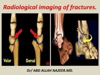
  • 1. Dr/ ABD ALLAH NAZEER.MD. Radiological imaging of fractures.
  • 2. The skull is formed by the fusion of several flat bones held together by the cranial sutures. Each of the flat bones consists of a thick outer table, the spongy diploe, and a thinner inner table. The inner table is lined by a thick, fibrous, adherent dura mater. A shallow subdural space lies between the inner surface of the dura and the thin arachnoid mater that covers the surface of the brain. Diagram of the cranium shows the anatomic layers. Diagram of the skull vault shows the location of various collections of fluid and/or blood.
  • 4. A skull fracture is a break in one or more of the eight bones that form the cranial portion of the skull, usually occurring as a result of blunt force trauma. If the force of the impact is excessive, the bone may fracture at or near the site of the impact and cause damage to the underlying physical structures contained within the skull such as the membranes, blood vessels, and brain. There are four major types of skull fractures: Linear Depressed Diastatic Basilar Linear fractures are the most common, and usually require no intervention for the fracture itself. Depressed fractures are usually comminuted, with broken portions of bone displaced inward— and may require surgical intervention to repair underlying tissue damage. Diastatic fractures widen the sutures of the skull and usually affect children under three. Basilar fractures are in the bones at the base of the skull.
  • 5.
  • 6. Linear skull fractures are breaks in the bone that transverse the full thickness of the skull from the outer to inner table. They are usually fairly straight with no bone displacement. The common cause of injury is blunt force trauma where the impact energy transferred over a wide area of the skull. Lateral skull radiograph in a child shows a long, linear fracture extending from the midline in the occipital region across the occipital bone into the temporal bone.
  • 7. Skull radiograph in a man shows a linear temporoparietal fracture. Lateral skull radiograph in a child shows a long, linear fracture running across the occipital bone.
  • 8. Linear skull fracture in the simple X-ray and 3 dimensional computed tomography. Linear skull fractures on the occipital bone (A and B) and parietal bone (C) show not in the simple X-ray but clearly in the 3 dimensional computed tomography.
  • 10. A depressed skull fracture is a type of fracture usually resulting from blunt force trauma, such as getting struck with a hammer, rock or getting kicked in the head. These types of fractures—which occur in 11% of severe head injuries—are comminuted fractures in which broken bones displace inward. Depressed skull fractures present a high risk of increased pressure on the brain, or a hemorrhage to the brain that crushes the delicate tissue. Plain radiographs of the head of a 25–year-old man who was assaulted with a baseball bat show a curvilinear shadow indicating a depressed fracture.
  • 12. Depressed skull fracture in the simple X-ray and 3 dimensional computed tomography. A : Depressed skull fracture on the parietal bone shows clearly both in the simple X-ray and 3 dimensional computed tomography. B and C : Depressed skull fracture on the outer table of the parietal bone shows not in the simple X-ray but clearly in the 3 dimensional computed tomography.
  • 13. Axial brain and bone-window computed tomography scans show multiple fractures involving the right temporal and parietal bones, with depression of several bone fragments into the brain around which contusional hemorrhage is present. Also present are soft-tissue swelling, air in the cranial cavity related to the bone fragments, and air in the subarachnoid space.
  • 14. Massive bifrontal infarction following massive depressed fracture overlying the superior sagittal sinus
  • 15. Diastatic fractures occur when the fracture line transverses one or more sutures of the skull causing a widening of the suture. While this type of fracture is usually seen in infants and young children as the sutures are not yet fused it can also occur in adults. When a diastatic fracture occurs in adults it usually affects the lambdoidal suture as this suture does not fully fuse in adults until about the age of 60. Postmortem radiograph in a child with multiple fractures due to non-accidental trauma show a diastatic fracture of the sagittal suture.
  • 16.
  • 17. Diastatic skull fractures in the simple X-ray and 3 dimensional computed tomography. A and B : Diastatic skull fractures on the lambdoid, temporo-parietal and occipito-mastoid sutures show clearly both in the simple X-ray and 3 dimensional computed tomography. C and D : Diastatic skull fractures on the coronal, lambdoid, and temporo-parietal sutures show not in the simple X-ray but clearly in the 3 dimensional computed tomography. Arrows.
  • 18. Top view from a shaded-surface display, in a different patient, shows a comminuted left temporofrontal fracture and diastasis of the metopic suture.
  • 19. Basilar skull fractures are linear fractures that occur in the floor of the cranial vault (skull base), which require more force to cause than other areas of the neurocranium. Thus they are rare, occurring as the only fracture in only 4% of severe head injury patients Axial computed tomography image demonstrating skull base fracture (arrow) through the petrous portion of the temporal bone.
  • 21. A growing skull fracture (GSF) also known as a craniocerebral erosion or leptomeningeal cyst due to the usual development of a cystic mass filled with cerebrospinal fluid is a rare complication of head injury usually associated with linear skull fractures of the parietal bone in children under 3. It has been reported in older children in atypical regions of the skull such as the basiooccipital and the base of the skull base and in association with other types of skull fractures. It is characterized by a diastatic enlargement of the fracture. Growing skull fracture or leptomeningeal cyst.
  • 22. CT scan brain showing growing skull fracture with underlying porencephalic cyst (a) before and (b) after repair Growing skull fracture.
  • 23. CT and MR images of the patient’s growing fracture.
  • 24. A cranial burst skull fracture usually occurring with severe injuries in infants less than 1 year of age is a closed, diastatic skull fracture with cerebral extrusion beyond the outer table of the skull under the intact scalp. Cranial burst skull fracture.
  • 25.
  • 26. A, Axial CT scan 3 hours after injury shows diastatic fracture with everted fracture edge and marked scalp swelling. Underlying subdural and subarachnoid hemorrhage and small cortical contusion are present. B, Coronal T2-weighted (3500/108/1) MR image 36 hours after injury reveals extent of cerebral herniation and dural defect. Note high signal intensity of both intracranial and extra-cranial brain tissue.
  • 27. A compound elevated skull fracture is a rare type of skull fracture where the fractured bone is elevated above the intact outer table of the skull. This type of skull fracture is always compound in nature. It can be caused during an assault with a weapon where the initial blow penetrates the skull and the underlying meninges and, on withdrawal, the weapon lifts the fractured portion of the skull outward. It can also be caused the skull rotating while being struck in a case of blunt force trauma, the skull rotating while striking an inanimate object as in a fall, or it may occur during transfer of a patient after an initial compound head injury. (a-c) Axial CT plain images bone window showing the elevated skull fracture of frontal bone with few displaced fracture fragments and pneumocephalus. Axial CT scan plain images brain window (d-f) showing parafalcine hemorrhage, hemorrhagic, and nonhemorrhagic contusions in frontal lobe, extracalvarial herniation of the brain parenchyma, and air pockets.
  • 28. Preoperative clinical photograph (a) and CT head (b,c,d) showing degloving scalp wound, avulsed bone flap and exposed dura
  • 29. Compound "elevated" fracture of the cranium.
  • 30. Compound fracture of the cranium with brain injury.
  • 31. Axial CT, shows “egg shell” type of skull fractures.
  • 32. (a) Brain CT scan revealing a large depressed fracture over left frontal region; (b) Brain CT scan with bone window to confirmed a large depressed fracture over left frontal region.
  • 33. Axial bone CT scan showing an occipital depressed skull fracture and penetration of left frontal and occipital region by the lion canines (arrow).
  • 34.
  • 35. Facial fractures are commonly caused by blunt or penetrating trauma sustained during motor vehicle accidents, assaults, and falls. The facial bones are thin and light making them susceptible to injury. Types complex fractures which involve multiple facial buttresses: naso-orbito-ethmoid (NOE) complex fracture Le Fort fractures zygomaticomaxillary complex fracture Complex mid-facial fracture fractures which involve a single facial buttress: frontal sinus fracture nasal bone fracture orbital blow-out fracture isolated zygomatic arch fractures paranasal sinus fractures alveolar process fractures mandibular fracture
  • 36. Facial Anatomy Three-dimensional CT images of an adult skull in frontal (a) and lateral oblique (b) orientations with color overlays show the superficial aspects of the horizontal and vertical facial buttresses and, in b, the sites of potential complications of fractures involving each buttress. The horizontal buttresses are the upper transverse maxillary (yellow), lower transverse maxillary (green), upper transverse mandibular (orange), and lower transverse mandibular (purple) buttresses. The vertical buttresses are the medial maxillary (red), lateral maxillary (blue), posterior maxillary (magenta), and posterior vertical mandibular (purple) buttresses.
  • 37. System of facial partitions. Three-dimensional CT image of an adult skull with color overlays shows partition of the facial anatomy into upper (red), middle (blue), and lower (yellow) thirds, the system used by otolaryngologists to describe locations of fracture in the facial anatomy.
  • 38. Complex Fractures Involving Multiple Facial Buttresses. Le Fort fractures are complex facial fractures that result from a high-force impact on the midface structures and are characterized by a variable degree of craniofacial dissociation spanning multiple facial buttresses. These fractures were first described in the early 20th century by French surgeon René Le Fort, who conducted experiments in which blunt force was applied to the midface of cadavers. Le Fort fractures. Three-dimensional CT images of an adult skull in frontal (a) and lateral (b) orientations with color overlays show the osseous facial structures that are typically affected by type I (red), type II (blue), and type III (yellow) Le Fort fractures.
  • 39. A type I Le Fort fracture, also known as a Guérin fracture or “floating palate,” results in separation of the hard palate (lower transverse maxillary buttress) from the remainder of the face and the skull base. This fracture pattern is horizontally oriented and spans the anterior, lateral, and medial maxillary walls, transecting the inferior margin of the pyriform aperture and nasal septum and extending posteriorly through the pterygoid plates. Because the fracture extends antero-posteriorly in the axial plane, it is typically best depicted on coronal and three-dimensional images.
  • 40. (a) Axial unenhanced CT image at an inferior level of the maxillary sinuses demonstrates bilateral fractures through the pterygoid plates (arrowheads) and maxillary sinus walls (red arrows), findings indicative of type I Le Fort fractures. Pterygomaxillary dissociation due to fracture extension through the pterygoid plate is a criterion for Le Fort classification. (b) Axial unenhanced CT image at a superior level of the maxillary sinuses depicts fractures through the medial margins of the anterior and posterior maxillary walls, which are characteristic of type II Le Fort fractures (blue arrows), and nondisplaced fractures through the zygomatic arch, which are a component of type III Le Fort fractures (yellow arrows). (c) Axial unenhanced CT image at the level of the orbits shows fractures through the nasal bridge, medial orbital walls, and lateral orbital walls (yellow arrows), findings indicative of type III Le Fort fractures. (d) Coronal unenhanced CT image demonstrates type I Le Fort fractures of the inferior aspect of the maxillary sinus walls (red arrows), type II Le Fort fractures of the inferomedial orbital walls (blue arrows), and type III Le Fort fractures of the medial and lateral orbital walls (yellow arrows). (e) Three- dimensional CT image in frontal orientation delineates type I (red), II (blue), and III (yellow) Le Fort fractures.
  • 41. (a) Three-dimensional CT image of facial bones demonstrates bilateral type I (red arrows) and type II (blue arrows) and left-sided type III (yellow arrows) Le Fort fractures. (b) Three- dimensional CT image obtained after internal fixation of the fractures shows plates and screws spanning the medial maxillary (red arrows), lateral maxillary (blue arrows), right lower transverse maxillary (green arrows), and right upper transverse maxillary (yellow arrow) buttresses. Maxillomandibular fixation devices also are seen (purple arrows).
  • 42. Three-dimensional CT image of the left medial maxillary buttress in lateral oblique orientation shows a single fracture fragment that includes the lacrimal fossa at the expected insertion site of the medial canthal tendon, findings indicative of a type I NOE fracture. Fractures through the left frontal calvaria, lateral orbital rim, and zygomatic arch also are seen.
  • 43. (a–c) Axial unenhanced CT images of the left orbital region show nondisplaced fractures through the left zygomaticofrontal (green arrow in a), zygomaticosphenoid (yellow arrow in b), zygomaticomaxillary (blue arrow in c), and zygomaticotemporal (red arrow in c) sutures. (d) Three- dimensional CT image of the upper left facial region shows a nondisplaced left zygomaticomaxillary complex fracture through the zygomaticofrontal (green arrow), zygomaticosphenoid (yellow arrow), zygomaticomaxillary (blue arrow), and zygomaticotemporal (red arrow) sutures.
  • 44. (a) Three-dimensional CT image of an adult face in oblique orientation depicts a right zygomaticomaxillary complex fracture with a nondisplaced zygomaticofrontal suture (green arrow), mildly displaced zygomaticomaxillary suture (blue arrow), and comminuted and displaced zygomatic arch extending through the zygomaticotemporal suture (red arrow); the zygomaticosphenoid suture was involved but is not depicted. A nondisplaced fracture of the base of the right coronoid process (arrowhead) also is seen. (b) Three-dimensional CT image in the same orientation demonstrates fixation of the zygomaticomaxillary and zygomaticotemporal sutures with plates and screws.
  • 45. Frontal sinus fracture. Axial unenhanced CT image of the frontal bone demonstrates a mildly displaced fracture of the anterior and posterior walls of the right frontal sinus with associated opacification of the right frontal sinus and small foci of pneumocephalus.
  • 46. Nasal bone fractures. (a) Axial unenhanced CT image shows a nondisplaced type 1 fracture through the right nasal bone. Chronic dehiscence of the left orbital plate of ethmoid bone is incidentally seen. (b) Axial unenhanced CT image depicts mildly comminuted and displaced type 2 fractures through the bilateral nasal bones and nasal septum.
  • 47. Zygomatic arch fracture. Axial unenhanced CT image demonstrates a comminuted and depressed fracture of the left zygomatic arch with resultant compression of the underlying temporalis muscle, a condition that could lead to trismus.
  • 48. Fracture of the maxillary alveolar process. Axial unenhanced CT image depicts a fracture of the maxillary alveolar process, with resultant avulsion of the medial and right lateral maxillary incisors.
  • 49. Orbital blowout fracture. Coronal unenhanced CT image shows a displaced blowout fracture of the left inferior orbital wall with resultant entrapment of the inferior rectus muscle (arrow), which appears rounded in comparison with the normal right inferior rectus muscle. The fracture extends through the inferior orbital canal (arrowhead).
  • 50. Orbital blowout fracture before and after fixation. (a) Coronal unenhanced CT image demonstrates a left inferior orbital blowout fracture with herniation of intraorbital fat and the inferior rectus muscle. (b) Coronal unenhanced CT image obtained after surgical fixation depicts metallic surgical mesh placed along the inferior orbital wall fracture. The position and appearance of the left inferior rectus muscle are normal. (c) Axial contrast- enhanced CT image obtained at follow-up shows dilatation and rim like enhancement of the left lacrimal duct (arrow), findings indicative of dacryocystitis secondary to lacrimal duct obstruction, a complication of either fracture or surgical fixation.
  • 51. Orbital roof fracture. Coronal unenhanced CT image demonstrates mild inferior displacement of a right orbital roof fracture with an adjacent extraconal hemorrhage.
  • 52. Three-dimensional CT image with color overlays shows the parts of the mandible in lateral orientation: the alveolar process (magenta), parasymphyseal region (blue), body (red), angle (green), ramus (yellow), coronoid process (orange), and condyle (purple).
  • 53. Axial unenhanced CT image of the mandible demonstrates a displaced fracture of the right mandibular angle with distraction of the mandibular canal (yellow arrow). (b, c) Axial (b) and three-dimensional (c) unenhanced CT images of the mandible after internal fixation of the right posterior aspect of the upper transverse mandibular buttress across the mandibular angle fracture (green arrow in c) and maxillomandibular fixation shows reapproximation of the right mandibular body fracture fragments and mandibular canal (yellow arrow in b).
  • 54. Mandibular fractures before and after internal fixation. (a) Axial unenhanced CT image of the mandible demonstrates a displaced fracture of the right mandibular angle with distraction of the mandibular canal (yellow arrow). (b,) Axial (b) and three-dimensional (c) unenhanced CT images of the mandible after internal fixation of the right posterior aspect of the upper transverse mandibular buttress across the mandibular angle fracture (green arrow in c) and maxillomandibular fixation shows reapproximation of the right mandibular body fracture fragments and mandibular canal (yellow arrow in b).
  • 55. Dental fracture as a complication of lower transverse maxillary buttress fracture. Sagittal unenhanced CT image of the facial midline demonstrates a maxillary alveolar process fracture that extends through the right medial maxillary incisor root (arrow).
  • 56. CSF leakage as a complication of medial maxillary buttress fracture. Coronal unenhanced CT image of the face depicts a comminuted fracture through the cribriform plate (arrow), a condition that may lead to CSF rhinorrhea. Fractures of the bilateral orbital roofs, which could cause dural tears, also are seen.
  • 57. Sinus obstruction as a complication of fracture of the nasolacrimal canal (medial maxillary buttress fracture). (a) Coronal unenhanced CT image demonstrates a blowout fracture of the left medial orbital wall with fracture fragments obstructing the left frontal recess (arrowhead), a condition that could lead to mucocele formation, which is not present in this case. (b) Axial unenhanced CT image at the level of the maxillary sinuses shows a minimally displaced fracture through the nasolacrimal canal (arrow), which could lead to disruption of the nasolacrimal duct.
  • 58. Telecanthus and optic nerve injury as complications of medial maxillary buttress fracture. Axial unenhanced CT image demonstrates a comminuted fracture of the NOE complex with telecanthus and involvement of the bilateral lacrimal fossae (arrows), findings indicative of a type III fracture of the NOE complex with medial canthal tendon avulsion. A fragment of the fractured right medial orbital wall impinges on the right optic nerve (arrowhead).
  • 59. Fractures through the lateral maxillary buttress also may extend to the superior orbital fissure or orbital apex, potentially leading to superior orbital fissure syndrome or orbital apex syndrome, respectively. The lateral canthal ligament may be injured at the site of its attachment to the lateral orbital wall.
  • 60. Involvement of the superior orbital fissure in a lateral maxillary buttress fracture. Axial unenhanced CT image demonstrates a mildly comminuted and displaced fracture of the left lateral orbital wall with extension to the superior orbital fissure (arrow). This finding, when combined with palsy of cranial nerves III, IV, V1, and VI, is indicative of superior orbital fissure syndrome.
  • 61. Complication of a posterior maxillary buttress fracture. Axial unenhanced CT image depicts comminuted fractures of the right anterior and posterior maxillary sinus walls and zygomatic arch. Extension of the fracture through the right foramen ovale (arrow) is suggestive of possible injury to the indwelling cranial nerve V3.
  • 62. Temporal Bone Anatomy and Fractures. Normal anatomy of the temporal bone. Axial high-resolution (a–e) and coronal MPR (f) multidetector CT images of the temporal bone show the external auditory canal (EAC), carotid canal (CC) and jugular bulb (JB), malleus (M), facial nerve (FN), cochlea (C), semicircular canals (SCC), internal auditory canal (IAC), incus (I), vestibule (V), vestibular aqueduct (VA), and mastoid air cells (MAC).
  • 63. Temporal bone fractures are usually a sequelae of blunt head injury, generally from severe trauma. Associated intracranial injuries, such as extra-axial haemorrhage, shear (or diffuse axonal) injury and brain contusion are common. Early identification of temporal bone trauma is essential to managing the injury and avoiding complications. Classification: direction Temporal bone fractures classically are described concerning the long axis of the petrous bone, being classified as: longitudinal fractures transverse fractures mixed fractures Classification: otic capsule involvement Other classifications have been proposed and are more clinically relevant. Temporal bone fractures can be classified based on: otic capsule sparing otic capsule violating Involvement of the otic capsule is a predictor of more serious complications including: facial nerve paralysis (2-5x as likely) CSF leak (4-8x as likely) sensorineural hearing loss (7-25x as likely) epidural haematoma and subarachnoid haemorrhage
  • 64. Longitudinal fracture. Axial high-resolution multidetector CT image of the temporal bone shows a longitudinal fracture (arrows) that extends into the middle ear. Transverse fracture. Axial high-resolution multidetector CT image of the temporal bone shows a transverse fracture (arrows) involving the semicircular canal, with opacification of the mastoid air cells.
  • 65. Mixed fracture. Axial high-resolution multidetector CT image of the temporal bone shows a fracture with transverse (arrows) and longitudinal (arrowhead) components, findings indicative of a mixed fracture.
  • 66. (a) Axial high-resolution multidetector CT image of the temporal bone shows an otic capsule–sparing fracture (arrows). (b) Axial high-resolution multidetector CT image of the temporal bone shows an otic capsule–violating fracture (arrows).
  • 67. External auditory canal. (a) Axial high-resolution multidetector CT image of the temporal bone shows the external auditory canal (arrows), which is intact. (b) In a different patient, axial multidetector CT image of the cervical spine shows a longitudinal fracture (arrowhead) that extends into the external auditory canal (arrows).
  • 68. Ossicles. (a) Axial high-resolution multidetector CT image of the temporal bone shows the normal incudomalleal relationship (arrowheads). (b) In a different patient, axial multidetector CT image of the cervical spine shows incudomalleal dislocation (arrow) secondary to a transverse fracture (arrowheads).
  • 69. The cochlea. (a) Axial high-resolution multidetector CT image of the temporal bone shows a normal cochlea (arrow). (b) In a different patient, axial multidetector CT image of the cervical spine shows a transverse fracture (arrowheads) that extends into the cochlea.
  • 70. The vestibule. (a) Axial high-resolution multidetector CT image of the temporal bone shows normal vestibule anatomy (arrow). (b) In a different patient, axial maxillofacial multidetector CT image shows a transverse fracture (arrowheads) that extends into the vestibule.
  • 71. The semicircular canals. (a) Axial high-resolution multidetector CT image of the temporal bone shows an intact semicircular canal (arrowheads). (b) In a different patient, axial high-resolution multidetector CT image of the temporal bone shows a subtle fracture line (arrowheads) that extends into the posterior semicircular canal.
  • 72. Cervical spine anatomy fractures. A-P view. Lateral View. Odontoid peg view
  • 73. A-P view. Lateral View. Odontoid peg view
  • 74. Cervical spine fractures can occur secondary to exaggerated flexion or extension, or because of direct trauma or axial loading. The four major mechanisms are flexion, extension, rotational and shearing, each associated with certain fracture patterns: flexion: most common mechanism anterior atlantoaxial subluxation anterior subluxation (hyperflexion sprain) anterior wedge fracture clay-shoveler fracture flexion teardrop fracture bilateral facet dislocation hyperflexion fracture-dislocation lateral flexion unilateral occipital condyle fracture lateral mass C1 fracture flexion-rotation unilateral facet dislocation rotatory atlantoaxial dislocation extension hangman fracture extension teardrop fracture posterior arch C1 fracture posterior atlantoaxial subluxation extension-rotation articular pillar fracture floating pillar axial loading/compression burst fracture (with axial loading) Jefferson fracture complex injuries atlantooccipital dissociation (shearing) occipital condyle fracture odontoid process fracture
  • 75. Jefferson fracture. The first image is the odontoid view, which illustrates the lateral displacement of C1. The second image is a coronal reconstruction from a CT, which confirms the findings from the odontoid view. The last image is a CT axial view, which clearly shows the location of the fractures of C1.
  • 76. Dens Fracture Type I Type I Odontoid fracture: fracture in superior tip of the odontoid. This type of fracture is potentially unstable. It is a relatively rare fracture
  • 77. Type II Odontoid Fracture: fracture at base of odontoid. It is the most common type of odontoid fracture. It is an unstable fracture.
  • 78. Dens type III fracture. The first image is an odontoid view, which shows the fracture line extending beyond the base of the dens. The second image is a CT that confirms the fracture in the body of C2.
  • 79. Hangman's Fracture Radiographic features: (best seen on lateral view) 1. Prevertebral soft tissue swelling. 2. Avulsion of anterior inferior corner of C2 associated with rupture of the anterior longitudinal ligament. 3. Anterior dislocation of the C2 vertebral body. 4. Bilateral C2 pars interarticularis fractures.
  • 80. Flexion Teardrop Fracture Radiographic features: (best seen on lateral view) 1. Prevertebral swelling associated with anterior longitudinal ligament tear. 2. Teardrop fragment from anterior vertebral body avulsion fracture. 3. Posterior vertebral body subluxation into the spinal canal. 4. Spinal cord compression from vertebral body displacement. 5. Fracture of the spinous process.
  • 82. Bilateral Facet Dislocation. Radiographic features: (best seen on lateral view) 1. Complete anterior dislocation of affected vertebral body by half or more of the vertebral body AP diameter. 2. Disruption of the posterior ligament complex and the anterior longitudinal ligament. 3. "Bow tie" or " bat wing" appearance of the locked facets.
  • 83. Bilateral interfacetal dislocation. 50% anteroposition C5C6 as a result of the dislocation. In unilateral dislocation the anteroposition is usually only 25%. Widened space between spinous processes C5 and C6 due to ligament rupture. Ruptured disc space.
  • 84. Bilateral interfacetal dislocation with complete transsection of the cord.
  • 85. Unilateral Facet Dislocation. Radiographic features: (best seen on lateral or oblique views) 1. Anterior dislocation of affected vertebral body by less than half of the vertebral body AP diameter. 2. Discordant rotation above and below involved level. 3. Facet within intervertebral foramen on oblique view. 4. Widening of the disk space. 5. "Bow tie" or "bat wing" appearance of the overriding locked facets.
  • 86. Unilateral interfacetal dislocation. On the axial view the left facet joint is normal and the configuration has similarities with the hamburger. On the right side the classic 'inverted hamburger sign' is seen. MRI-findings are: Spinal cord lesion, which can be described as contusion, edema or non-hemorrhagic spinal cord injury. Rupture of the spinous ligaments. Rupture of the ligamentum flavum. Rupture of the disc with migration of disc material on the posterior side of C4 and even on the anterior side of C5.
  • 87. Clay Shoveler's Fracture Radiographic features: (best seen on lateral view) 1. Spinous process fracture on lateral view. 2. Ghost sign on AP view (i.e. double spinous process of C6 or C7 resulting from displaced fractured spinous process).
  • 88. Wedge Fracture. Radiographic features: 1. Buckled anterior cortex. 2. Loss of height of anterior vertebral body. 3. Anterosuperior fracture of vertebral body.
  • 91. The Thoraco-Lumbar Injury Classification and Severity score (TLICS) is a classification system for thoracolumbar spine injuries, designed to assist in clinical management.
  • 92.
  • 93.
  • 94.
  • 96. Pitfalls in diagnosing a compression fracture are: Congenital anomalies Osteochondrosis with irregular endplates Limbus vertebrae
  • 97.
  • 98. Retropulsion of posterosuperior vertebral body fragment.
  • 99. Burst fracture with posterior vertebral body fragment.
  • 100. Burst fracture with posterior vertebral body fragment.
  • 101.
  • 102.
  • 103.
  • 105.
  • 106. Severe compression of the vertebral body. However the most important findings are the horizontal fractures of the posterior elements.
  • 107. Spinous process distraction fracture with disruption of the ligamentum flavum and a partial disruption of the interspinous ligament.
  • 108. Distraction injury + PLC disruption.
  • 109. Burst Fracture with PLC injury: very subtle widening of right facet joint.
  • 110. Bilateral facet joint dislocation with anterior vertebral translation, PLC: always disrupted in translation.
  • 111. Unilateral facet joint dislocation with anterior vertebral translation, PLC: always disrupted in translation.
  • 112. Shoulder Anatomy and fractures. Anteroposterior (a), Grashey (b), and axillary (c) radiographs of the shoulder show normal glenohumeral alignment. The proximal humerus is composed of an anatomic head (black line), greater tuberosity (white line in a and b), lesser tuberosity (brown line), and surgical neck (brown shading in a and b). The joint capsule attaches at the anatomic neck of the humeral head (arrows in b). The glenoid process of the lateral scapula is formed by the glenoid fossa (yellow shading) and glenoid neck (blue lines). Superiorly, the base of the coracoid process (gold contourline) demarcates the anatomic glenoid neck (black arrowheads in a and b) and surgical glenoid neck (white arrowheads in a and b).
  • 113. (a) Axillary radiograph of the shoulder shows a fracture of the surgical neck (SN) and disruption of the normally smooth contour of the articular surface (arrow). (b, c) Oblique sagittal CT images of the shoulder obtained through the articular surface medially (b) and the proximal humerus more laterally (c) help confirm a comminuted fracture of the anatomic head with three articular fragments. The lesser tuberosity (LT) accompanies fragment 1, whereas fragment 2 contains the greater tuberosity (GT). Fragment 3 is separated (albeit minimally) from both tuberosities.
  • 114. Comminuted fracture that includes the surgical neck (SN), greater tuberosity (GT), and lesser tuberosity (LT), as well as anteroinferior dislocation of the anatomic head (AH).
  • 115. Bony Bankart and Hill-Sachs lesions in a 54-year-old man with chronic anterior shoulder instability.
  • 116. Small Hill-Sachs lesion in a 43-year-old man with recurrent dislocations
  • 117. Posterior glenohumeral dislocation in a 40-year-old man with alcohol-related seizures
  • 118. Unstable anterior glenoid rim fracture (Ideberg type Ia injury)
  • 119. Fracture of the glenoid surgical neck with SSSC disruption AP of the shoulder shows fracture of the glenoid surgical neck (arrows) with a concomitant fracture of the midclavicular shaft (arrowheads), findings that represent the most common configuration of floating shoulder.
  • 120. Scapula fractures are uncommon injuries, representing ~3% of all shoulder fractures. Classification intra-articular glenoid fracture type I: avulsion of anterior glenoid margin type II: transverse or oblique fracture through glenoid fossa exiting inferiorly type III: oblique fracture through glenoid fossa exiting superiorly and associated with acromioclavicular joint injury type IV: transverse fracture exiting through medial scapular border type V: combination of type II and type IV type VI: comminuted glenoid fracture extra-articular glenoid fracture type I: glenoid neck fracture without clavicular fracture type II: glenoid neck fracture with clavicular fracture and acromioclavicular dislocation coracoid process fracture type I: fracture proximal to the coracoclavicular ligament type II: fracture distal to the coracoclavicular ligament acromial fracture type I: minimally displaced type II: displaced but does not reduce subacromial space type III: displaced and narrow the subacromial space
  • 121. Acute displaced intraarticular fracture from glenoid to inferior portion of neck (Ideberg type 2). Coronal volume-rendered 3D CT image shows acute comminuted and displaced fracture extending from glenoid articular surface to base of coracoid process (Ideberg type 3)
  • 122. Anteroposterior radiograph shows acute anterior shoulder dislocation. Sagittal volume-rendered 3D CT image shows acute fracture and anterior displacement of large fracture fragment (arrow) from anterior glenoid rim (Ideberg type 1). Axial T2-weighted fat-saturated image shows acute displaced bony Bankart fracture at anterior inferior glenoid rim (long arrow) with associated bone marrow edema at posterolateral head (short arrow).
  • 123. Axillary radiograph shows acute fracture of coracoid process with anterior displacement of more than 1 cm (line). Axial CT image shows acute displaced coracoid fracture (black arrow) and deep Hill-Sachs impaction fracture at posterolateral humeral head (white arrow) after anterior shoulder dislocation.
  • 124. Anteroposterior radiograph shows displaced scapular neck (black arrow) and ipsilateral midshaft clavicle (long white arrow) fractures. Multiple ipsilateral displaced rib fractures are also present (short white arrows). Sagittal volume-rendered 3D CT image shows degree of scapular neck angulation and translation to greater detail. Degree of displacement and comminution of clavicle fracture is also better shown.
  • 125. Anteroposterior radiograph shows acute scapular neck fracture (black arrow) and Rockwood type III acromioclavicular joint separation (white arrow). Sagittal volume-rendered 3D CT image shows degree of scapular neck angulation in greater detail.
  • 126. Clavicular fractures are common and account for 2.6-10% of all fractures. They usually require minimal treatment, which relies on analgesia and a collar-and-cuff. However, in some cases open reduction and internal fixation is required. Radiology reports should not only include whether or not a fracture is present but also comment on: Fracture location of the fracture along the shaft angulation and fracture end displacement (including direction) comminution degree of overlap (measurement is useful) Associated findings and relevant negatives acromioclavicular joint and sternoclavicular joint alignment coracoclavicular distance glenohumeral joint Associated traumatic injuries rib fractures vertebral fractures scapular fractures (floating shoulder) pneumothorax
  • 127. Type 1 clavicular fracture (middle third). Type 2 clavicular fracture (lateral third).
  • 128. Type 1 comminuted clavicular fracture with skin tenting.
  • 130. Type 3 clavicular fracture (medial third).
  • 131. Type 3 acromioclavicular (AC) dislocation. Type 2 acromioclavicular (AC) dislocation.
  • 132. Medial clavicular fracture without injury to the sternoclavicular (SC) joint.
  • 133. Proximal humeral fractures are common upper extremity fractures, particularly in older patients, and can result in significant disability. Reporting checklist In addition to reporting the presence of a fracture it is important to assess and comment on a number of other features. Fracture: it should be noted that in most instances a description of the fracture rather than a specific classification is sufficient, but the features required to classify the fracture should be included location of fracture lines displacement and angulation of each part (> 1cm and >45 degrees respectively is particularly important in the Neer classification) presence of involvement of the articular surface Associated injuries: shoulder dislocation acromioclavicular dislocation scapular fracture clavicle fracture distal radial fracture (especially Colles fracture).
  • 134.
  • 135.
  • 137. Elbow Anatomy and Fractures.
  • 138. Normal elbow. Anterior humeral line and radiocapitellar line on normal lateral radiograph. The anterior humeral line is drawn along the anterior cortex of the distal humeral shaft and should bisect the middle third of the capitellum. The radiocapitellar line is parallel to the long axis of the radial neck and should bisect the capitellum. These were originally reported for evaluation of the pediatric elbow and have not been validated in adults. Elbow, fractures and dislocations. Elbow effusion with associated fat-pad elevation in the setting of radial head fracture. The anterior fat pad is elevated, and its undersurface is convex, giving the "spinnaker sail sign." The posterior fat pad is elevated out of the deep olecranon fossa and is visible just above the cortex of the distal humerus.
  • 139. Normal anterior fat pad. Positive fat pad sign both anteriorly as well as posteriorly.
  • 140. Supracondylar fractures. In A the anterior humeral line passes through the anterior third of the capitellum and in B even more anteriorly. Notice positive posterior fat pad sign in both cases
  • 141. Gartland type III fracture Gartland III fracture with medial-lateral cross pin technique. After reduction there is inadequate correction of medial collapse. After two months there is malunion with cubitus varus deformity.
  • 142. MR of lateral condyle fracture. Milch II and unstable elbow. T2 image with fat saturation on the right shows cartilaginous fracture. Fracture-fragment surrounded by synovial fluid.
  • 144. Capitellum fracture. Avulsion of medial epicondyle.
  • 145. On AP-view the avulsed medial epicondyle projects over the trochlea. Lateral view shows the fragment to be trapped within the joint. Avulsion of the medial epicondyle. The amount of soft tissue swelling on the medial side suggests that the elbow was dislocated. Subtle radial neck fracture seen only on AP-view.
  • 146. Radial neck fracture with tilt. Normal olecranon ossification centers in a patient with a tilted radial neck fracture. Olecranon fractures.
  • 148. Radiocapitellar view. What appears to be an isolated fracture of capitellum on anterio-posterior and true lateral view demonstrates an associated fracture of coronoid on radiocapitellar view
  • 149. Fracture of the shaft of the humerus. A and B, Anteroposterior and lateral radiographs demonstrate a comminuted fracture of the distal third of the humerus with a large butterfly fragment (arrows). The butterfly fragment is pulled medially and posteriorly, while the distal fragment (arrowheads) is retracted proximally due to the pull by the deltoid muscle.
  • 150. Fractures of distal humerus. A and B, Anteroposterior and lateral radiographs of the elbow show a comminuted transverse extra-articular metaphyseal fracture (type A) (arrows) with medial and volar displacement of the distal fragment. C and D, Transtrochlear fracture (partial articular, type B) (arrows) with mild displacement. The fracture extends from the trochlea to the lateral column of the distal humerus. E and F, Complete articular fracture (type C) with marked displacement. The fracture lines extend to both medial and lateral columns (arrows) of the distal humerus, as well as to the articular surface of the elbow (arrowhead). Distinction between type B and type C is based on the number of columns involved.
  • 151. Fractures of the radial head and olecranon process. A, Lateral radiograph of the elbow demonstrates a classic posterior fat pad sign (arrows) produced by posterior bulge of the extra synovial fat. In addition, there is an elevated anterior fat pad (white arrowheads). The cause of the joint effusion is a radial head fracture (black arrowhead). B, The black arrowhead demonstrates a nondisplaced fracture of the radial head. C, Lateral radiograph of the elbow shows a transverse fracture of the olecranon process (black arrowhead), a posterior fat pad sign (arrows), and elevated anterior fat pad (white arrowheads).
  • 152. Elbow dislocation and fracture of the coronoid process. Lateral radiograph of the elbow demonstrates a posterior dislocation of the radius and ulna with respect to the distal humerus. A coronoid process fracture is noted (arrowheads).
  • 153. Monteggia fracture-dislocation. A, Lateral radiograph of the forearm demonstrates dorsal dislocation of the radial head (black arrowheads), along with an angulated comminuted fracture of the proximal third of the ulna (arrows). Soft tissue gas indicates an open injury. This is a type II Monteggia fracture- dislocation. B, Volumetric (3D) CT reformation reveals an impacted fracture of the radial head (white arrowhead) along with the Monteggia fracture-dislocation.
  • 154. Forearm fractures are a group of fractures that occur in the forearm following trauma. The radius and ulna are bound together at the proximal and distal radioulnar joints and act as a ring. Radial or ulnar fracture will be visible on at least one view. It is important to determine what type of fracture it is, e.g. transverse, oblique, comminuted. If there is only one fracture, it is important to look for a second fracture, or see if there is damage to the proximal or distal radioulnar joint: Monteggia fracture-dislocation: radial fracture and dislocation of the radial head at the elbow Galeazzi fracture-dislocation: radial fracture dislocation of the distal ulna from the carpus. Galeazzi fracture-dislocations
  • 155. Galeazzi fracture-dislocation. A and B, Lateral and anteroposterior radiographs of the forearm show a displaced transverse fracture of the radial shaft at the junction of the middle and distal thirds, along with dislocation of the distal radioulnar joint (DRUJ). Dislocation of the radius relative to the ulna on the lateral radiograph and radial foreshortening (double-headed arrow) are clues suggesting DRUJ disruption.
  • 158. Combined Monteggia and Galeazzi fractures.
  • 159. Wrist anatomy and fractures.
  • 160.
  • 161. A Colles' fracture is a fracture of the distal metaphysis of the radius with dorsal angulation and displacement leading to a 'silver fork deformity'.
  • 162. Smith's fractures occur in younger patients and are the result of high energy trauma on the volar flexed wrist. Volar comminution and intraarticular extension are more common.
  • 163. Volar-type Barton's is a fracture-dislocation of the volar rim of the radius. Dorsal-type Barton's is a fracture- dislocation of the dorsal rim of the radius.
  • 165. Chauffeur's fracture An isolated fracture of the radial styloid process is also called a Hutchinson's or chauffeur's fracture.
  • 166. Ulnar styloid process fracture An ulnar styloid process fracture is usually associated with radial fractures and rarely isolated.
  • 167. Torus fractures, or buckle fractures, are extremely common injuries in children. Because children have softer bones, one side of the bone may buckle. The word torus is derived from the Latin word 'Tori' meaning swelling or protuberance. These injuries tend to heal much more quickly than the similar greenstick fractures.
  • 169. Epiphysiolysis fracture. These are usually Salter Harris type II epiphysiolysis fractures.
  • 170. Scaphoid fractures (i.e. fractures through the scaphoid bone) are common, in some instances can be difficult to diagnose, and can result in significant functional impairment. Fractures can occur essentially anywhere along the scaphoid, but distribution is not even 9: Waist of scaphoid: 70-80% Proximal pole: 20% Distal pole (or so-called scaphoid tubercle): 10% Scaphoid Fractures
  • 172. The lateral wrist projection image demonstrates a convincing positive pronator quadratus soft tissue sign and a complete transverse fracture of the lunate The PA wrist projection image was largely unremarkable (arguably some soft tissue signs)
  • 173. Fracture of the Lunate
  • 174. Triquetral fracture. There is a small avulsion from the dorsum of the triquetrum seen only on the lateral projection (red arrow). The pisiform overlies the triquetrum in the AP and oblique views and tends to obscure the fracture (white arrows).
  • 175. A coronal T1-weighted image of the wrist showing a radio-graphically occult capitate fracture (arrows).
  • 176. Pelvic fractures can be simple or complex and can involve any part of the bony pelvis. Pelvic fractures can be fatal, and an unstable pelvis requires immediate management. Classification Four main forces have been described in high-energy blunt force trauma that results in unstable pelvic fractures: Anteroposterior compression: result in an open book or sprung pelvis fractures Lateral compression: result in a windswept pelvis Vertical shear: results in Malgaigne fracture or bucket handle fracture Combined mechanical: occur when two different force vectors are involved and results in a complex fracture pattern Isolated stable pelvic fractures can also occur in the context of lower energy mechanisms or sporting injuries: acetabular fracture pubic ramus fracture iliac wing fracture (Duverney fracture) avulsion fractures (e.g. ASIS, iliac crest, ischial tuberosity)
  • 177. Computer-generated lateral view of the pelvis shows the three components of each of the paired innominate bones: ilium (yellow), ischium (orange), and pubis (green). The borders between the three bones are determined by the location of the immature physeal triradiate cartilage, which is fully fused by adulthood. Computer-generated image shows the stabilizing structures of the pelvic ring. The bony pelvic ring (blue circle) is made up of the sacrum and bilateral innominate bones and stabilized by the SI (1), sacrospinous (2), and sacrotuberous (3) ligaments. Secondary stabilization is provided by the iliolumbar ligaments (*). Anatomy and Biomechanics of the Pelvis
  • 178. Pelvic apophyseal avulsion fractures diagram
  • 179. lateral compression type 1 lateral compression type 2 lateral compression type 3 lateral compression type 3
  • 180. Young and Burgess classification of pelvic ring injury. Computer-generated images show lateral compression type 1 (a), lateral compression type 2 (b), lateral compression type 3 (c), AP compression type 1 (d), AP compression type 2 (e), AP compression type 3 (f), and vertical shear (g) fractures.
  • 181.
  • 182. Pelvic open book fracture
  • 185. Lateral compression type 1 injury in two patients.
  • 186. Lateral compression type 2 injury in an 18-year-old woman who was an unrestrained driver in a motor vehicle accident. (a) Pelvic radiograph shows left-sided overlapping superior and inferior pubic rami fractures (white arrows) and widening of the left SI joint (black arrow). (b) Axial CT image shows a fracture of the anterior sacrum at the site of the anterior SI ligament attachment (black arrow) and widening of the SI joint. A crescent fracture (white arrow) involving the left iliac bone is also seen. The posterior SI ligament is keeping the fragment attached to the sacrum. (c) Coronal CT image obtained at the level of the posterior SI joint shows the crescent fracture (black arrow). No craniocaudal displacement of the iliac bone (white arrow) is seen, a finding that excludes vertical shear injury.
  • 189. Combined lateral compression and vertical shear injury.
  • 191.
  • 192. Anterior wall acetabular fracture. A computed tomography (CT) scan demonstrates an oblique fracture through the anterior wall of the left acetabulum (arrow). Such fractures are uncommon in isolation. The patient had other pelvic injuries Computed tomography (CT) scan of a posterior wall acetabular fracture. The oblique fracture of the left acetabulum is clearly depicted. The degree of displacement and marginal impaction can be determined more accurately with CT scanning than with radiography.
  • 193. Both-column acetabular fracture. Anteroposterior pelvic radiograph (A), bilateral oblique pelvic radiographs (B, C), axial CT scan (D), and sagittal reconstruction CT scan (E) show acetabular fracture (straight arrows, A- C), with break in obturator ring (arrowheads, A-C) and extension into iliac wing (curved arrows). Note coronal plane of fracture on CT and superior pubic ramus fractured at puboacetabular junction.
  • 194. T-shaped acetabular fracture. Anteroposterior pelvic radiograph (A), bilateral oblique pelvic radiographs (B, C), axial CT scan (D), and surface- rendering 3D CT scan viewed laterally (E), with right hemipelvis and femur removed, show obturator ring fractures (arrowheads) and transverse component (arrows) through acetabulum. Note characteristic oblique-sagittal orientation of transverse acetabular fracture component on CT scans that is transverse relative to acetabulum on radiographs.
  • 195. Transverse acetabular fracture. Anteroposterior pelvic radiograph (A), bilateral oblique pelvic radiographs (B, C), axial CT scan (D), and surface-rendering 3D CT scan viewed laterally (E), with right hemipelvis and femur removed, show fracture (arrows) orientation transverse to acetabulum, disrupting iliopectineal and ilioischial lines (arrowheads). Note characteristic sagittal-oblique fracture plane on CT scan (D).
  • 196. Transverse with posterior wall acetabular fracture. Anteroposterior pelvic radiograph (A), bilateral oblique pelvic radiographs (B, C), axial CT scan (D), and surface-rendering 3D CT scan viewed laterally (E), with right hemipelvis and femur removed, show transverse fracture (straight arrows) disrupting iliopectineal and ilioischial lines (arrowheads) with displaced and comminuted posterior wall fracture fragment (curved arrows).
  • 197. Isolated posterior wall acetabular fracture. Anteroposterior pelvic radiograph (A), bilateral oblique pelvic radiographs (B, C), axial CT images (D, E), and parasagittal reconstruction CT image (F) show displaced fracture fragments (curved arrows) from isolated posterior wall fracture (straight arrow, D).
  • 198. Transverse with posterior wall acetabular fracture. An anteroposterior radiograph of the pelvis shows that the central dislocation of the left femoral head results in the disruption of the iliopectineal and ilioischial lines. In addition, the left posterior acetabular wall is disrupted. left obturator oblique view of the pelvis view better demonstrates the anterior column and posterior wall disruption. (CT) scan of a transverse fracture with a posterior wall acetabular fracture
  • 199. Both-column acetabular fracture, X-Ray and CT images.
  • 200. There are several classification systems for sacral fractures, but the most commonly employed are the Denis classification and subclassification systems, and the Isler classification system. These classification systems are important to understand as proper classification can impact management. Denis classification zone 1: fracture involves the sacral ala lateral to the neural foramina zone 2: fracture involves the neural foramina, but does not involve the spinal canal zone 3: fracture is medial to the neural foramen, involving the spinal canal; these may be transverse or longitudinal, and can be sub-classified into 4 types: type 1: only kyphotic angulation at the fracture site (no translation) type 2: kyphotic angulation with anterior translation of the distal sacrum type 3: kyphotic angulation with complete offset of the fracture fragments type 4: comminuted S1 segment, usually due to axial compression Morphologic injury patterns of zone 3 fractures “H” shaped fracture “U” shaped fracture “ʎ” shaped fracture (lambda) “T” shaped fracture Isler classification Used for fractures that involve the lumbosacral articulation: Isler 1: fracture occurs lateral to the L5/S1 facet Isler 2: fractures line involves the L5/S1 facet Isler 3: fracture line extends medially to the L5/S1 facet
  • 201.
  • 203. (A) Sagittal initial CT scan shows type 1 upper sacral fracture with an anterior simple bending of the upper sacrum fragment. (B) Simple initial lateral radiogram shows upper sacral non-displaced fracture. (C) Simple radiologic image shows no differences between initial and 6 months follow up studies.
  • 204. (A) Sagittal initial CT scan shows type 2 upper sacral fracture with a posterior displacement of the upper fragment. (B) Simple initial lateral radiogram shows comminuted fractures with displacement. (C) Simple radiologic image shows malunion at 4 months follow up studies.
  • 205. (A) Sagittal preoperative CT scan shows type 2 upper sacral fracture with a posterior displacement of the upper fragment. (B) Axial preoperative CT scan shows narrowing of sacral canal due to posterior translation of bony fragment. (C) Axial CT scan after laminectomy at level S1-S2 shows elimination of posterior wall of sacral canal. (D) Sagittal CT scan shows malunion of fracture site at 3 months follow up studies.
  • 206. Initial computed tomography scan shows a displaced comminuted sacral fracture with narrowing of the sacral canal at the S1-S2 level. (A) and axial T1-weighted magnetic resonance (B), T2-weighted magnetic resonance (C) images showing left S1 nerve root compression due to a displaced S1 sacral body and hematoma.
  • 207. Computed tomography scan with an isolated S5 fracture after a same-level fall.
  • 208. Fractures of the coccyx are thought to be trivial injuries, however, they can take a long while to heal. (Chronic coccyx pain is termed coccydynia). The coccyx is broken by a direct blow, such as a fall on the buttocks. Another less common mechanism is by pressure from the passage of the fetus down the birth canal during delivery.
  • 209. Four examples of posterior luxation (dislocation of a joint, with the lower joint surface slipping backwards)
  • 211. CT scan of broken sacrum and coccyx
  • 212. Image showing edema around coccygeal segment.
  • 213. Femoral Neck Anatomy and fractures.
  • 214. Neck of femur fractures (NOF) are common injuries sustained by older patients who are both more likely to have unsteadiness of gait and reduced bone mineral density, predisposing to fracture. Elderly osteoporotic women are at greatest risk. Classification Femoral neck fractures are a subset of proximal femoral fractures. The femoral neck is the weakest part of the femur. Since disruption of blood supply to the femoral head is dependent on the type of fracture and causes significant morbidity, diagnosis and classification of these fractures is important. Neck of femur fractures are considered intracapsular fractures (also called proximal femoral fractures). Intracapsular fractures include: Subcapital: femoral head/neck junction Transcervical: midportion of femoral neck Basicervical: base of femoral neck
  • 215. Valgus- and varus-impacted subcapital fractures. (a) Anteroposterior radiograph in an 88-year-old woman who had sustained a fall demonstrates characteristic valgus angulation of the proximal fracture fragment, a finding that is most evident due to the presence of subtle cortical overlap of the lateral femoral neck and head cortex forming a triangular opacity (arrow). (b) Anteroposterior radiograph of the hip in a 66-year- old woman who had sustained a fall shows a varus-impacted fracture, which can be distinguished from the more common valgus-impacted variant on the basis of the presence of a triangular opacity representing medial cortical overlap (small arrow), along with a displaced lateral cortical fracture (large arrow). (c) Coronal CT image of the hip in a 68-year-old woman shows a varus-impacted fracture with medial cortical overlap (triangular opacity [small arrow]), as well as a prominent, inferiorly projecting cortical rim, a finding that is often mistaken for an osteophyte (mushroom cap deformity) (large arrow).
  • 216. Osteoporosis and complaints of groin pain. (a) Initial anteroposterior radiograph demonstrates focal disruption of the lateral femoral cortex (white arrow) with the fracture line oriented perpendicular to the primary tensile trabeculae (black arrows). The patient was diagnosed with an incomplete insufficiency-type stress fracture and was placed under strict activity restrictions. (b) Follow-up anteroposterior radiograph obtained after acute atraumatic exacerbation of groin pain demonstrates completion of the now-displaced femoral neck fracture (arrow).
  • 217. Intertrochanteric fractures with various morphologic features in women between ages 65 and 80 years. (a) Anteroposterior radiograph shows a type 1 fracture, which is apparent only as a nondisplaced fracture line extending through the lateral and medial cortex (arrow). (b) Anteroposterior radiograph obtained in a different patient shows a type 2 fracture that is moderately displaced but still reflects a mechanically stable injury (arrow). (c) Anteroposterior radiograph obtained in a third patient shows a more severe type 5 fracture with comminution of both the posteromedial (small arrow) and posterolateral (large arrow) cortices, findings that indicate a highly unstable injury.
  • 218. Sub-capital hip fracture. On the frontal view, there is a step-off in the cortex superiorly (red arrow) while there is abnormal overlapping of the femoral head and neck (white arrows) due to impaction. On the lateral view, the same step-off can be seen (red arrow) as well as the impaction (white arrow).
  • 219. X-ray of fracture shaft femur.
  • 221. Knee anatomy and fractures.
  • 222. Avulsion fractures of the knee are numerous due to the many ligaments and tendons inserting around this joint. They include 1: Anterior cruciate ligament avulsion fracture Posterior cruciate ligament avulsion fracture Avulsion of the medial collateral ligament origin of MCL avulsion fracture: Stieda fracture insertion of deep fibers: reverse Segond fracture Avulsion fracture of the deep fibers avulsion fracture of the insertion of superficial fibers of MCL: 5 cm below the joint line Avulsion of the lateral collateral ligament: origin of LCL: above popliteal groove conjoined tendon: fibular head below the tip, biceps femoris and insertion of LCL avulsion fracture arcuate ligament complex avulsion fracture (arcuate sign) Segond fracture iliotibial band avulsion fracture: Gerdy tubercle Semimembranosus tendon avulsion fracture patellar fractures quadriceps tendon avulsion fracture patellar sleeve fractures chronic injuries Osgood-Schlatter disease Sinding-Larsen-Johansson syndrome Jumper's knee
  • 223. Segond fracture is an avulsion fracture of the knee that involves the lateral aspect of the tibial plateau and is very frequently (~75% of cases) associated with disruption of the anterior cruciate ligament (ACL) tear. Segond fracture.
  • 224.
  • 225. Segond fracture and bony avulsion of ACL.
  • 227. Tibial plateau fractures. Line drawings of Schatzker types I, II, and III tibial plateau fractures. Tibial plateau fractures. Line drawings of Schatzker types IV, V, and VI tibial plateau fractures.
  • 228. Tibial plateau fractures. Radiograph of the knee shows lateral plateau splitting, a Schatzker I injury. There is no articular depression. Tibial plateau fractures. A different patient illustrates a Schatzker II injury with subtle lateral articular depression.
  • 229. Tibial plateau fractures. Axial CT image of the same patient as in the previous image shows the extent of the lateral tibial plateau fracture. In this case, it extends to the lateral tibial margin and an associated fibular head fracture is seen. This is a Schatzker II injury.
  • 230. Tibial plateau fractures. Radiograph of the knee reveals fractures through both the medial and the lateral tibial plateau along with a fibular head fracture and a fracture through the tibial metaphysis. This is a Schatzker VI injury. Tibial plateau fractures. Radiograph of the knee shows a different Schatzker VI fracture.
  • 231. Tibial plateau fractures. Axial and coronal reformatted CT image demonstrates the extensive fractures of both the lateral and medial aspects of the tibial plateau, a Schatzker VI injury.
  • 232. Tibial plateau fractures. Coronal reformatted CT. Initial narrow collimation axial CT data can be reconstructed into sagittal and coronal planes. This technique is useful to evaluate for fracture lines parallel to the axial imaging plane, degree of articular depression, and degree of diastasis between major fracture fragments. The best reconstructions are made when the initial data set consists of axial images of less than 2 mm thickness. In this particular case, an axial data set of 1 mm images was reconstructed into this coronal image demonstrating fractures of the tibial spines.
  • 233. AP image and lateral image (mediolateral projection) of an intercondylar eminence fracture.
  • 234.
  • 235.
  • 236. AP image, lateral image (mediolateral projection) and axial image. The vertical fracture is clearly visible on the axial image and subtly identifiable on the AP image.
  • 237. Hoffa fracture of the medial femoral condyle sustained after being hit with a bat. AP ( a ) and lateral ( b ) knee radiographs demonstrating a coronally oriented fracture ( arrow ) of the medial femoral condyle, and a suprapatellar joint effusion ( arrowhead ). The fracture is not appreciated on the AP view. Sagittal ( c ) and shaded
  • 239.
  • 240.
  • 241.
  • 242. Basically there are three main types of ankle fractures. Weber classified them as: type A - infrasyndesmotic type B - transsyndesmotic type C - suprasyndesmotic These fractures are identical to the fractures described by Lauge-Hansen as supination- adduction, supination-exorotation and pronation-exorotation. We will first give a short overview of these fractures and then discuss them in more detail.
  • 243. Weber A Occurs below the syndesmosis, which is intact. According to Lauge-Hansen, it is the result of an adduction force on the supinated foot. Stage 1 - Tension on the lateral collateral ligaments results in rupture of the ligaments or avulsion of the lateral malleolus below the syndesmosis. Stage 2 - Oblique fracture of the medial malleolus.
  • 244. Weber B This is a transsyndesmotic fracture with usually partial - and less commonly, total - rupture of the syndesmosis. According to Lauge-Hansen, it is the result of an exorotation force on the supinated foot. Stage 1 - Rupture of the anterior syndesmosis Stage 2 - Oblique fracture of the fibula (this is the true Weber B fracture) Stage 3 - Rupture of the posterior syndesmosis or - fracture of the malleolus tertius Stage 4 - Avulsion of the medial malleolus or - rupture of the medial collateral bands
  • 245. Weber C This is a fracture above the level of the syndesmosis. Usually there is a total rupture of the syndesmosis with instability of the ankle. According to Lauge-Hansen, it is the result of an exorotation force on the pronated foot. Stage 1 - Avulsion of the medial malleolus or - ligamentous rupture Stage 2 - Rupture of the anterior syndesmosis Stage 3 - Fibula fracture above the level of the syndesmosis (this is the true Weber C fracture) Stage 4 - Avulsion of the malleolus tertius or - rupture of the posterior syndesmosis
  • 246. Weber and Lauge-Hansen summary Weber A = Infrasyndesmotic Avulsion of the lateral malleolus Oblique fracture of the medial malleolus (uncommon) Weber B = Transsyndesmotic Rupture of the anterior syndesmosis Oblique fracture of the fibula Rupture of the posterior syndesmosis or - fracture of the malleolus tertius Avulsion of the medial malleolus - or - rupture of the medial bands Weber C = Suprasyndesmotic Avulsion of the medial malleolus or - ligamentous rupture Rupture of the anterior syndesmosis Fibula fracture above the level of the syndesmosis Avulsion of the malleolus tertius or - rupture of the posterior syndesmosis
  • 248. Weber type A fractures, stage 1.
  • 249. Weber A - stage 2
  • 250. Stage 1: Rupture of anterior tibiofibular ligament - or avulsion fracture (Tilleaux)
  • 251. Weber B - stage 3 and 4
  • 253. Weber C fracture - stage 3.
  • 254. Weber C fracture - at least stage 3
  • 255. Weber C fracture - stage 4
  • 256. Trimalleolar Weber B fracture
  • 257. The Salter-Harris classification describes fractures that involve the epiphyseal plate or growth plate. The most common is type II, which accounts for 75%. Type I - transverse fracture through the growth plate or physis Type II - fracture through the growth plate and the metaphysis, sparing the epiphysis Type III - fracture through growth plate and epiphysis, sparing the metaphysis Type IV - fracture through all three elements of the bone, the growth plate, metaphysis, and epiphysis Type V - compression fracture of the growth plate These Salter-Harris fractures can be easily missed. In many cases there is only minimal or no displacement. The fracture through the growth plate is usually obscure and difficult to differentiate from normal variations of the growth plate. And finally we tend not to look carefully at the epiphysis.
  • 258. Type I Salter-Harris fractures
  • 259. Type 11 Salter-Harris fractures.
  • 260. Type III is a fracture through the growth plate and epiphysis sparing the metaphysis.
  • 263.
  • 266. Calcaneal fractures are the most common tarsal fracture, and can occur in a variety of settings. Calcaneal fractures can be divided broadly into two types depending on whether there is articular involvement of the subtalar joint: extra-articular: 25-30% anterior calcaneal process fracture calcaneal tuberosity avulsion fracture extra-articular body fracture lover's fracture medial sustentaculum intra-articular: 70-75% intra-articular body fracture The calcaneus is also a common site of stress fractures, occurring in the posterosuperior aspect. Another method of classification is as Type A fractures: the anterior process of the calcaneus is fractured type B: fracture of the mid calcaneus, trochlear process, and sustentaculum tali Type C: fracture of the posterior tuberosity
  • 268. (a) Lateral radiograph shows a joint depression type fracture, with the fracture line exiting at the inferior calcaneal surface (arrow). (b) Lateral radiograph shows a tongue type fracture, with the fracture line exiting at the posterior calcaneal surface (arrow). Note also the joint depression type fracture line (arrowhead).
  • 269. (a) and axial (b) multidetector CT scans of the right foot show a severe comminuted calcaneal fracture involving the lateral (*), central (arrow), and medial (arrowhead) aspects relative to the posterior facet and subtalar joint.
  • 270. Hawkins-Canale type I talar neck fracture. Sagittal reformatted CT image of the ankle shows a nondisplaced fracture (arrow) through the talar neck. Note the inferior extension of the fracture anterior to the posterior subtalar facet, defining the talar neck location.
  • 271. Hawkins-Canale type II talar neck fracture. Lateral radiograph (a) and sagittal reformatted CT image (b) of the ankle show a vertical fracture of the talar neck (arrow in a) and dislocation of the posterior subtalar facet (arrowhead)
  • 272. Hawkins-Canale type III talar neck fracture. (a) AP radiograph of the ankle shows subtalar and tibiotalar dislocation and lateral extrusion of the talar body. (b) Lateral radiograph of the ankle shows the vertical fracture line through the talar neck (arrow). Gas and edema in the soft tissues are consistent with open injury (arrowhead). (c) Three-dimensional reconstructed CT image of the ankle (in another patient) shows a talar neck fracture, tibiotalar and subtalar dislocation, and medial talar body extrusion.
  • 273. Hawkins-Canale type IV talar neck fracture. (a) AP radiograph of the ankle shows tibiotalar and subtalar dislocation with lateral extrusion of the talar body. Subtle offset at the talonavicular joint is also seen (arrowhead). (b) Lateral radiograph of the ankle shows the vertical fracture line through the talar neck (arrow) and malalignment at the talar head (arrowhead).
  • 274. Talar dislocation. (a) Lateral radiograph of the ankle shows tibiotalar, talonavicular, and talocalcaneal dislocations. The talus is rotated and extruded anteriorly and laterally. (b) AP radiograph of the ankle shows disruption of the ankle mortise and lateral displacement of the talus.
  • 275. CT images in the axial (A), coronal (B), and sagittal (C) planes demonstrate a chronic, ununited navicular stress fracture complicated by osteonecrosis and fragmentation.
  • 278. Lisfranc Fracture-Dislocation. The bases of all of the metatarsals are dislocated laterally in this homolateral Lisfranc dislocation. There was a fracture of the base of the 2nd metatarsal.
  • 279. Stage II Lisfranc injury
  • 280. Rib fractures are a common consequence of trauma and can cause life- threatening complications. Aetiology blunt and penetrating trauma: e.g. motor vehicle accidents, falls, assaults most common injury in blunt thoracic trauma, occurring in 50% of cases 3 pathological fractures stress fractures: occur more commonly in high-level athletes non-accidental injuries in children typically posterior fractures cardiopulmonary resuscitation (CPR): occurs in 1 in 3 fetal rib fractures: caused by skeletal dysplasias radiation induced rib fractures Associations Rib fractures are often associated with other injuries and the greater the number of rib fractures the more likely are associated injuries: brachial plexus or subclavian vessel injuries (1st-3rd rib fractures) pneumothorax/hemothorax pulmonary laceration lung herniation liver, kidney and spleen traumatic injuries (10-12th rib fractures)
  • 281. Multiple bilateral rib fractures of different ages. Left-sided rib fractures (arrowheads) appear to have callus formation, while the right sided fractures (arrows) do not. Note right pleural effusion/thickening laterally.
  • 282. Coronal MIP CT image showing multiple contiguous left rib fractures (arrows)
  • 284. Old posterior rib fractures very indicative of non accidental trauma.
  • 285.
  • 286. Healing Rib Fractures. Chest radiograph on left demonstrates multiple rib fractures with bony callus about the fracture sites (white arrows). The close-up image from a rib series again demonstrates multiple displaced healing rib fractures (red arrows).
  • 287. Flail Chest. Radiograph demonstrates multiple rib fractures (black arrows) with some ribs fractured in two or more places. There is also a pulmonary contusion (red arrow) and subcutaneous emphysema (white arrow)
  • 288. 3 D volumetric reconstruction of a patient presenting following a road traffic accident. This shows multiple right sided rib fractures at more than two sites (asterisks) denoting flail chest
  • 289. Axial images through the thorax of a motorcyclist who drive directly into a rubbish skip. An emergency left pneumonectomy was performed, and a post-operative CT scan of the chest with IV contrast on mediastinal [A] and lung windows [B], shows left sided pleural fluid. The density of the fluid was -23 HU suggestive of high fat content and therefore chylothorax, secondary to cisterna chyli injury.