
Recomendados
Recomendados
Mais conteúdo relacionado
Mais procurados
Mais procurados (20)
Destaque
Destaque (20)
Semelhante a Stabilizing Linear and Rotary Inverted Pendulum Systems
Semelhante a Stabilizing Linear and Rotary Inverted Pendulum Systems (20)
Último
Último (20)
Stabilizing Linear and Rotary Inverted Pendulum Systems
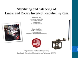
- 1. Stabilizing and balancing of Linear and Rotary Inverted Pendulum system. Presented by- Nowab Md. Aminul Haq Student ID. -1010130 Ashik-E-Rasul Student ID. 1010132 Department of Mechanical Engineering Bangladesh University of Engineering and Technology (BUET) 1 Supervised by- Dr. Md. Zahurul Haq Professor & Head. Department of Mechanical Engineering, BUET.
- 2. What is an Inverted Pendulum ? 2 A Pendulum that has its center of mass above its pivot point. • Inherently unstable. • Must be actively balanced in order to remain upright. • Must have a feedback system to keep it balanced. Criteria for Balancing • Moving the Pivot point . • Applying torque at the Pivot point. • Generating a net torque on the Pendulum. • Vertically Oscillating the Pivot point.
- 4. Types of Inverted Pendulum 4 In general two types- 1. Linear Inverted Pendulum 2. Rotary Inverted Pendulum Moving the pivot point horizontally Applying a torque at the pivot point
- 5. Our Thesis Work 5 Inverted pendulum pivoted on cart Rotary Inverted pendulumSelf Balancing Vehicle prototype Linear Inverted Pendulum
- 7. Methodology of work 7 Study of System dynamics Mathematical Modeling MATLAB Simulation PID Controller design in MATLAB Application of Controller in Experimental Setup.
- 8. System Dynamics and Mathematical Modeling 8 • 2D problem, where the pendulum is constrained to move in the vertical plane. • Control input is the force , F that moves the cart horizontally. • Outputs are the angular position of the pendulum and the horizontal position , of the cart . • Pendulum is vertically upright , when = pi System Transfer Functions
- 9. MATLAB Simulation of the System. 9 Time phi • No Feedback, No Controller. • The System goes without bound. • The pendulum falls down within seconds. Fig: System behavior without Feedback and Controller.
- 10. PID Controller Design 10 Angle Fig: Simulink Model of the system with PID controller and Feedback Fig: System block diagram with PID controller and Feedback PID Controller Proportional gain , KP Integral gain, KI Derivative gain, KD • Angular displacement is sent as a feedback. • Displacement can me measured by using Sensor( Potentiometer, Encoder , Gyroscope etc. )
- 11. PID Controller design in MATLAB 11 Initialization KP = 1,KI= 1,KD =1 Tuning KP between( 1-100) Tuning KD between( 1-20)
- 12. 12 PID Controller design in MATLAB Tuned Response, with KP=100, KI=1, KD=20
- 13. Application of Controller in Experimental Setup. 13 Res ult
- 14. Rotary Inverted Pendulum 14 Fig: ExperimentalFig: Rotary Inverted Pendulum
- 15. Mathematical Modeling 15 Equation of Motion Linearization State Space Model Open loop poles MATLAB Plot Fig: Mathematical modeling result
- 16. Pole Plotting on MATLAB 16 Fig: Open Loop Poles
- 17. Controller Design(Pole Placement Method) 17 Controll ability Desired Poles • ζ = 0.7. • ωn = 4 rad/s • |α| < 15 deg. • Gain Calculat ion • To move the poles to desired location Simulati on • Simulate The result To Model • Apply on the system 2 . . . ] ( ) [ n Ran T B k AB A B A B T n 3 430, 40p p
- 22. Designing an optimal controller 22 Linear Quadratic Regulator(LQR) Cost Function Design Matrices • Design Matrices(Q and R) with trial and error • Control effort(Vm) is limited Gain • Calculate Controller Gain Using MATLAB Simulation • Done in Simulink To Model • Apply on the Model
- 26. 26 Motor Voltage
- 27. 27 PendulumAngle
- 28. 28 ArmAngle
- 29. 29 Concluding Remarks • Experiment study of Linear Inverted Pendulum, considering both the Pendulum Angle and cart position. • Balancing can be studied with other modern controllers, ex. Fuzzy Controller, Neural Network etc. • A comperative study of different controllers can also be done, to analyze which controller provides the best Balancing.
- 30. Thank you!! 30