
Recomendados
Mais conteúdo relacionado
Mais procurados
Mais procurados (20)
Semelhante a Renr88830001
Semelhante a Renr88830001 (20)
Último
Último (20)
Renr88830001
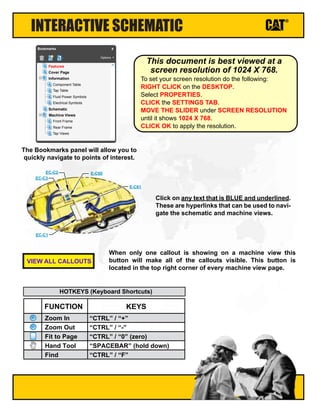
- 1. INTERACTIVE SCHEMATIC The Bookmarks panel will allow you to quickly navigate to points of interest. Click on any text that is BLUE and underlined. These are hyperlinks that can be used to navi- gate the schematic and machine views. When only one callout is showing on a machine view this button will make all of the callouts visible. This button is located in the top right corner of every machine view page. VIEW ALL CALLOUTS Cover Page Information Schematic Machine Views Component Table Tap Table Fluid Power Symbols Electrical Symbols Front Frame Rear Frame Tap Views Features Options Bookmarks X EC-C3 EC-C2 E-C60 EC-C1 E-C61 To set your screen resolution do the following: RIGHT CLICK on the DESKTOP. Select PROPERTIES. CLICK the SETTINGS TAB. MOVE THE SLIDER under SCREEN RESOLUTION until it shows 1024 X 768. CLICK OK to apply the resolution. This document is best viewed at a screen resolution of 1024 X 768. FUNCTION Zoom In HOTKEYS (Keyboard Shortcuts) Zoom Out Fit to Page Hand Tool “CTRL” / “+” KEYS “CTRL” / “-” “CTRL” / “0” (zero) “SPACEBAR” (hold down) Find “CTRL” / “F”
- 2. Electrical System 525C, 535C, and 545C Wheel Skidder 525C: 5251-451 535C: 5351-272 545C: 5451-377 2006 Caterpillar, All Rights Reserved Printed in U.S.A. © RENR8883-01 September 2006
- 3. Page 1 of 2 COMPONENT LOCATION Component Schematic Location Machine Location Component Schematic Location Machine Location Air Seat Attachment F-13 22 Resistor - Blower E-15 B Alarm - Action J-11 A Resistor - Dash Terminator J-11 A Alarm - Backup A-18 11 Resistor - Engine Terminating F-6 21 Alternator - 80A B-4 24 Sender - Fuel Level A-18 11 Battery - 1 L-2 12 Sensor - Atmosphereic Pressure H-1 33 Battery - 2 L-1 12 Sensor - Boost Pressure H-1 34 Breaker - AIH A-6 15 Sensor - Engine Coolant Temperature I-1 30 Breaker - Alternator B-6 15 Sensor - Engine Oil Pressure G-1 29 Breaker - Machine Control A-6 15 Sensor - Grapple Pressure A-18 11 Breaker - Main A-6 15 Sensor - Hydraulic Oil Temperature E-4 20 Buss Bar D-4 13 Sensor - Intake Manifold Air Temperature I-1 35 Control - Cable Winch B-15 B Sensor - Primary Steer K-3 19 Control - Decking Blade B-15 B Sensor - Rail Pressure G-1 31 Control - Engine I-3 25 Sensor - Throttle Position I-7 2 Control - Grapple (Fixed) B-15 B Sensor - Torque Converter Temperature J-18 10 Control - Machine B-11 3 Sensor - Transmission Out Speed J-18 10 Control - Steering H-12 1 Sensors - Engine Speed Timing H-1 28 Converter - 24 To 12 Volts K-11 A Solenoid - 1 Forward High I-18 10 Floodlamp - LH Corner 1 L-6 6 Solenoid - 2 Reverse I-18 10 Floodlamp - LH Corner 2 L-6 6 Solenoid - 3 Forward Low I-18 10 Floodlamp - LH Front I-7 6 Solenoid - 4 Speed 1 Clutch I-18 10 Floodlamp - LH Rear K-16 5 Solenoid - 5 Speed 2 Clutch I-18 10 Floodlamp - LH Rear Corner 1 L-16 5 Solenoid - 6 Speed 3 Clutch I-18 10 Floodlamp - LH Rear Corner 2 L-16 5 Solenoid - A/C Clutch F-4 37 Floodlamp - RH Corner 1 L-6 6 Solenoid - Brake Off Cable F-18 18 Floodlamp - RH Corner2 K-6 6 Solenoid - Deck Blade Down C-5 19 Floodlamp - RH Front I-7 6 Solenoid - Deck Blade Up C-5 19 Floodlamp - RH Rear K-16 5 Solenoid - Differential Lock D-15 B Floodlamp - RH Rear Corner 1 G-17 5 Solenoid - Ether Start G-6 21 Floodlamp - RH Rear Corner 2 G-17 5 Solenoid - Free Spool Cable F-18 18 Fuse Block A-8 8 Solenoid - Free Spool E/H D-18 16 Gound - RH Compartment A-15 2 Solenoid - Grapple CCW Rotate B-18 11 Ground - Dash K-12 A Solenoid - Grapple CW Rotate B-18 11 Ground - Engine Block 1 E-3 39 Solenoid - Grapple Tong Close B-18 11 Ground - Engine Block 2 C-5 47 Solenoid - Grapple Tong Open B-18 11 Ground - Engine Block 3 B-4 24 Solenoid - IAP Control I-1 32 Ground - Frame 1 L-3 14 Solenoid - Lockup Clutch J-18 10 Ground - Frame 2 B-5 15 Solenoid - Park Brake D-4 20 Ground - Frame 2 F-10 3 Solenoid - Proportional Brake Cable E-18 18 Ground - Roof H-15 C Solenoid - Reel In Cable E-18 18 Heater - Air Intake E-3 26 Solenoid - Reel In E/H D-18 11 Horn - Forward C-6 23 Solenoid - Reel Out E/H D-18 11 Injector - Cylinder #1 J-4 41 Solenoid - Winch High Low E/H D-18 17 Injector - Cylinder #2 J-3 42 Suppressor - Arc Free Spool Cable F-18 18 Injector - Cylinder #3 J-3 43 Suppressor - Arc Free Spool E/H E-18 16 Injector - Cylinder #4 J-3 44 Suppressor - Arc A/C F-4 37 Injector - Cylinder #5 J-3 45 Suppressor - Arc Brake Off Cable E-18 18 Injector - Cylinder #6 J-3 46 Suppressor - Arc Reel In Cable E-18 18 Instrument - Cluster K-8 A Suppressor - Arc Reel In E/H D-18 11 Lamp - Dome 1 H-15 4 Suppressor - Arc Reel Out E/H D-18 11 Motor - Defroster Fan Group L-11 7 Switch - AC On E-15 B Motor - Front Washer E-4 21 Switch - Accumulator Charge Pressure E-4 20 Motor - Front Wiper J-7 6 Switch - Blower E-16 B Motor - Fuel Transfer Pump D-4 21 Switch - Defrost Fan L-14 C Motor - LH Blower H-18 9 Switch - Differential Lock D-15 B Motor - Rear Washer F-4 21 Switch - Disconnect L-2 14
- 4. Page 2 of 2 COMPONENT LOCATION Component Schematic Location Machine Location Component Schematic Location Machine Location Motor - Rear Wiper F-17 5 Switch - Engine Shutdown D-5 14 Motor - RH Blower H-18 9 Switch - Forward Horn H-12 1 Motor - Secondary Steer L-2 38 Switch - Free Spool C-15 B Motor - Starter C-5 27 Switch - Front Lamp I-14 C Plug - Accessory 12V C-8 8 Switch - Front Rear Washer K-14 C Receptacle - Auxilary Start L-2 14 Switch - Front Wiper K-14 C Relay - AIH E-3 26 Switch - Key Start I-12 A Relay - Decking Blade Return E-8 8 Switch - Lock Up Clutch Enable I-12 A Relay - Front Attachment Floodlamp J-15 C Switch - Operator Mode Select J-12 A Relay - Fuel Transfer Pump D-8 8 Switch - Park Brake I-12 A Relay - Grapple Floodlamp J-15 C Switch - Park Brake Pressure E-4 20 Relay - Grapple Solenoid Return C-8 8 Switch - Rear And Attachment Lamp J-14 C Relay - Main B-8 8 Switch - Rear Wiper J-14 C Relay - Rear Attachment Floodlamp I-15 C Switch - Reel In C-15 B Relay - Secondary Steering Intermediate E-8 8 Switch - Reel Out D-15 B Relay - Start B-6 15 Switch - Refrigerant Pressure F-4 37 Relay - Winch Free Spool D-8 8 Switch - Secondary Steer Test J-12 A Relay - Winch Reel Out D-8 8 Switch - Secondary Steer Pressure K-3 38 Relay - Winch Solenoid Return D-8 8 Switch - Transmission Filter Pressure D-5 19 Relay - Winch Wheel In E-8 8 Thermostat H-17 9 Machine locations are repeated for components located close together. A = Located inside of dash. B= Located inside of right instrument control panel. C = Located inside of overhead panel.
- 5. CONNECTOR LOCATION Connector Number Schematic Location Machine Location CONN 1 J-16 10 CONN 2 I-16 10 CONN 3 H-17 9 CONN 4 D-17, E-17 11 CONN 5 C-18 11 CONN 6 B-17 11 CONN 7 B-17 11 CONN 8 H-15 C CONN 9 K-15 5 CONN 10 G-13 8 CONN 11 H-11 A CONN 12 MSS J-11 A CONN 13 Service Tool J-11 A CONN 14 L-10 C CONN 15 L-10 7 CONN 16 H-7 19 CONN 17 H-7 19 CONN 18 L-7 6 CONN 19 E-6 20 CONN 20 G-6 20 CONN 21 K-4 10 CONN 22 J-2 40 CONN 23 TDC Probe I-1 37 CONN 24 Fuel Interface H-1 36 The connectors shown in this chart are for harness to harness connectors. Connectors that join a harness to a component are generally located at or near the component. See the Component Location Chart.
- 6. CID / MID / FMI Failure Mode Identifiers (FMI)¹ FMI No. Failure Description 0 Data valid but above normal operational range. 1 Data valid but below normal operational range. 2 Data erratic, intermittent, or incorrect. 3 Voltage above normal or shorted high. 4 Voltage below normal or shorted low. 5 Current below normal or open circuit. 6 Current above normal or grounded circuit. 7 Mechanical system not responding properly. 8 Abnormal frequency, pulse width, or period. 9 Abnormal update. 10 Abnormal rate of change. 11 Failure mode not identifiable. 12 Bad device or component. 13 Out of calibration. 14 Parameter failures. 15 Parameter failures. 16 Parameter not available. 17 Module not responding. 18 Sensor supply fault. 19 Condition not met. 20 Parameter failures. ¹The FMI is a diagnostic code that indicates what type of failure has occurred. Component Identifiers (CID¹) Module Identifier (MID²) Engine Control System (MID No. 036) CID Component 0001 Injector Cylinder #1 0002 Injector Cylinder #2 0003 Injector Cylinder #3 0004 Injector Cylinder #4 0005 Injector Cylinder #5 0006 Injector Cylinder #6 0041 8 Volt DC Supply 0042 Inject Actuation Control Valve 0091 Throttle Position Signal 0094 Fuel Pressure 0100 Engine Oil Pressure 0110 Engine Coolant Temperature 0164 Injector Actuation Pressure 0168 Electrical System Voltage 0172 Intake Manifold Air Temperature 0190 Engine Speed Signal 0253 Personality Module 0261 Engine Timing Calibration 0262 5 Volt DC Supply 0267 Engine Shutdown Switch 0268 Check Programmable Parameters 0296 Transmission ECM 0342 Secondary Engine Speed Signal 0617 Air Inlet Heater Relay 1627 Fuel Pump Relay 1639 Machine Security System Module 1785 Intake Manifold Pressure Sensor 2417 Ether Injection Control Solenoid Machine Control System (MID No. 039) CID Component 0041 8 Volt Sensor Power Supply 0070 Parking Brake Switch 0096 Fuel Level Sensor 0168 Electrical System Voltage 0191 Transmission Output Speed Sensor 0246 Proprietary CAN Data Link 0262 5 Volt Sensor Power Supply 0268 Programmed Parameter Fault 0271 Action Alarm 0444 Starter Motor Relay 0449 Grapple Rotate Switch 0450 Tong Position Switch 0451 Grapple Clockwise Switch 0452 Grapple Counter-Clockwise Switch 0453 Tong Open Solenoid 0454 Tong Close Solenoid 0455 Auto Grab Pressure Sensor 0590 Engine Control Module 0600 Hydraulic Oil Temperature Sensor 0621 Downshift Switch 0622 Upshift Switch 0623 Directional Switch 0627 Parking Brake Switch 0679 Torque Converter Lockup Solenoid 0681 Parking Brake Solenoid 0740 Differential Lock Solenoid 0793 Primary Steering Pressure Sensor 0794 Secondary Steering Pressure Sensor 0795 Secondary Steering Intermediate Relay 0826 Torque Converter Oil Temperature Sensor 1046 Power Train Oil Filter Bypass Switch 1078 Blade Control Handle Sensor 1197 Blade Lower Solenoid 1198 Blade Raise Solenoid 1272 Brake Oil Accumulator Pressure Switch 1326 ECM Location Code 1401 Transmission 1 Solenoid 1402 Transmission 2 Solenoid 1403 Transmission 3 Solenoid 1404 Transmission 4 Solenoid 1405 Transmission 5 Solenoid 1406 Transmission 6 Solenoid 1884 Winch Spool In Solenoid 1885 Winch Spool Out Solenoid 1887 Winch Low Speed Lock Solenoid 1941 Auto Tong Switch 2267 Winch Control Handle Position Sensor 2268 Winch Free Spool Solenoid 2438 Winch Free Spool Switch 2470 Primary Steering Pressure Sensor ¹ The CID is a diagnostic code that indicates which circuit is faulty. ² The MID is a diagnostic code that indicates which electronic control module diagnosed the fault. Event Code Condition E194 High Exhaust Temperature E198 Low Fuel Pressure E265 User Defined Shutdown E360 Low Engine Oil Pressure E361 High Engine Coolant Temperature E362 Engine Overspeed E390 Fuel Filter Restriction E441 Idle Elevated To Increase Battery Voltage E539 High Intake Manifold Air Temperature Engine Event Codes
- 7. SPECIFICATIONS AND RELATED MANUALS Off Machine Switch Specification Part No. Function Actuate Deactuate Contact Position 3E-5464 Thermostat -1.1 ± 0.8°C (30 ± 1.4°F) 2.2 ± 0.8°C (36 ± 1.4°F) Normally Closed 3E-7806 Accumulator Charge Pressure 9500 kPa MAX (1375 psi MAX) 8300 ± 350 kPa (1200 ± 50 psi) (A-B) Normally Open (A-C) Normally Closed 3E-7808 Secondary Steering Pressure 1100 kPa MAX (160 psi MAX) 860 ± 170 kPa (125 ± 25 psi) Normally Closed 114 -5333 Refrigerant Pressure 275 to 1750 kPa¹ (40 to 255 psi) - - - - Normally Open² 174-4312 Park Brake Pressure 8270 kPa MAX (1199 psi MAX) 6890 ± 345 kPa (999 ± 50 psi) (A-B) Normally Open (A-C) Normally Closed 227-6744 Transmission Filter Pressure 276 ± 28 kPa (40 ± 4 psi) 179 kPa MIN (26 psi MIN) Normally Closed ¹ With increasing pressure the closed condition can be maintained up to 2800 kpa (405 psi), with decreasing pressure the closed condition can be maintained down to 170 kpa (25psi). ² Contact position at the contacts of the harness connector. Resistor, Sender and Solenoid Specifications Part No. Component Description Resistance (Ohms)¹ 3E-1906 Solenoid: A/C Clutch 17 ± 0.6 116-4152 Solenoid: Differential Lock 34.3 ±1.7 134-2540 Resistor: Data Link Terminating (Engine & Dash) 120 ± 12 166-3388 Sender: Fuel Level Empty 92 to 98 Full 0 to 3.5 239-1134 Solenoid: Ether Start 20 240-6822 Solenoid: 1 Forward High 2 Reverse 3 Forward Low 4 Speed 1 Clutch 5 Speed 2 Clutch 6 Speed 3 Clutch 31.1 ± 2.4 244-3114 Solenoid: Lockup Clutch 8.7 ± 0.4 252-0741 Solenoid: Park Brake 26.96 ± 1.35 253-1763 Solenoid: Deck Blade Up Deck Blade Down 8.7 ± 0.4 8.7 ± 0.4 257-6364 Solenoid: Free Spool Hydraulic 3.5 ± 0.5 ¹ At room temperature unless otherwise noted. Related Electrical Service Manuals Form Number Alternator: 177-9953 SENR4130 Electric Starting Motor: 207-1561 SENR3581 Engine Control: RENR9320 Machine Control: RENR8952 Title
- 8. HARNESS and WIRE Electrical Schematic Symbols 1 2 AG-C4 111-7898 L-C12 3E-5179 9X-1123 Component Part Number Pin or Socket Number Part Number: for Connector Receptacle Part Number: for Connector Plug Harness Identification Letter(s): (A, B, C, ..., AA, AB, AC, ...) Plug 325-AG135 PK-14 Wire Color Wire Gauge Receptacle Pressure Symbol T Temperature Symbol Level Symbol Flow Symbol Circuit Breaker Symbol Harness and Wire Symbols 1 1 2 2 Sure-Seal connector: Typical representation of a Sure-Seal connector. The plug and receptacle contain both pins and sockets. Deutsch connector: Typical representation of a Deutsch connector. The plug contains all sockets and the receptacle contains all pins. Symbols Symbols and Definitions Fuse (5 Amps) 5A T Fuse: A component in an electrical circuit that will open the circuit if too much current flows through it. Switch (Normally Open): A switch that will close at a specified point (temp, press, etc.). The circle indicates that the component has screw terminals and a wire can be disconnected from it. Switch (Normally Closed): A switch that will open at a specified point (temp, press, etc.). No circle indicates that the wire cannot be disconnected from the component. Ground (Wired): This indicates that the component is connected to a grounded wire. The grounded wire is fastened to the machine. Ground (Case): This indicates that the component does not have a wire connected to ground. It is grounded by being fastened to the machine. Reed Switch: A switch whose contacts are controlled by a magnet. A magnet closes the contacts of a normally open reed switch; it opens the contacts of a normally closed reed switch. Sender: A component that is used with a temperature or pressure gauge. The sender measures the temperature or pressure. Its resistance changes to give an indication to the gauge of the temperature or pressure. Relay (Magnetic Switch): A relay is an electrical component that is activated by electricity. It has a coil that makes an electromagnet when current flows through it. The electromagnet can open or close the switch part of the relay. Solenoid: A solenoid is an electrical component that is activated by electricity. It has a coil that makes an electromagnet when current flows through it. The electromagnet can open or close a valve or move a piece of metal that can do work. Magnetic Latch Solenoid: A magnetic latch solenoid is an electrical component that is activated by electricity and held latched by a permanent magnet. It has two coils (latch and unlatch) that make electromagnet when current flows through them. It also has an internal switch that places the latch coil circuit open at the time the coil latches. Harness identification code: This example indicates wire group 325, wire 135 in harness "AG". L-C12 3E-5179 Wire, Cable, or Harness Assembly Identification: Includes Harness Identification Letters and Harness Connector Serialization Codes (see sample). Harness Connector Serialization Code: The "C" stands for "Connector" and the number indicates which connector in the harness (C1, C2, C3, ...).
- 9. Components are shown installed on a fully operable machine with the key and engine off, transmission shifter in neutral and with parking brake set. Refer to the appropriate Service Manual for Troubleshooting, Specifications and Systems Operations. SCHEMATIC PART NUMBER: 257-5927, CHANGE: 00, VERSION: - THIS SCHEMATIC IS FOR THE 525C, 535C, AND 545C WHEEL SKIDDER ELECTRICAL SYSTEM MEDIA NUMBER: RENR8883-01 WIRES THAT HAVE SYSTEM VOLTAGE WHEN THE KEY SWITCH IS OFF. WIRES THAT HAVE SYSTEM VOLTAGE WHEN THE KEY SWITCH IS ON. VOLTAGE CONVERTER OUTPUT CIRCUIT. STARTING CIRCUIT. GROUND CIRCUIT. STARTING AID CIRCUIT. ENGINE CONTROL CIRCUIT. MACHINE CONTROL CIRCUIT. HEATER AND AIR CONDITIONER CIRCUIT. WIPER/WASHER CIRCUIT. WIRE GROUP COLOR DESCRIPTIONS CAN DATA LINK A. CAT DATA LINK. 1 2 3 4 5 6 7 8 X-C1 1552264 1 2 X-C2 3E5179 3 4 5 6 7 8 9 10 11 12 DOWNSHIFT (N/O) DOWNSHIFT (N/C) UPSHIFT (N/O) UPSHIFT (N/C) REVERSE SW FORWARD SW BR-20 GROUND NEUTRAL SW PU-20 BK-20 BU-20 GY-20 WH-20 YL-20 (1) STEERING CONTROL 145-9994 GN-20 (1) FORWARD HORN SW 2T-3360 1 2 W-C15 3E3364 1 2 W-C64 1552269 1 2 W-C63 1552269 A B C D E F W-C8 9X4814 1 2 W-C12 1552252 3 4 5 6 7 8 9 10 11 12 1 2 W-C25 1552269 W-C32 9W1951 A B C D E F G H J 1 2 W-C6 1552269 1 2 W-C37 1552252 3 4 5 6 7 8 9 10 11 12 1 2 W-C70 1552269 1 2 W-C71 1552269 1 2 W-C41 1552273 3 4 5 6 1 5 2 4 3 W-C49 1195094 1 5 2 4 3 W-C51 1195094 1 2 W-C52 1552273 3 4 5 6 1 2 W-C58 1552264 3 4 5 6 7 8 1 5 2 4 3 W-C50 1195094 1 2 W-C7 1552269 1 2 W-C26 3E3364 1 2 W-C36 1552272 3 4 W-C56 1552267 A B C W-C55 3E3370 A B C W-C42 3E3382 1 2 3 4 5 6 7 8 W-C61 3E3388 W-C67 1552267 A B C 15A 15A BLOWER AIR SEAT 15A 15A WIPERS 12V CONVERTER 15A 10A ENGINE DEFROST FAN 15A 15A REAR CORNER LIGHTS 15A 10A REAR/GRAPPLE LIGHTS 15A 10A SPARE CORNER LIGHTS 10A 10A KEY SWITCH DOME LAMP 15A 15A FORWARD FLOODLAMP 12V CONVERTER SWITCHED BUS UNSWITCHED BUS GAGES 2 4 6 8 10 12 14 16 15 13 11 9 7 5 3 1 TRANSMISSION W-C39 1617337 10A 10A GAGES HORN 20A 15A ENGINE SPARE 17 18 19 20 1 2 W-C38 7T5957 1 2 W-C59 1552269 1 2 W-C60 3E3364 1 2 W-C20 1552252 3 4 5 6 7 8 9 10 11 12 1 2 W-C65 1552273 3 4 5 6 W-C66 3E3382 W-C68 3E3370 A B C 1 2 3 4 5 6 7 8 9 10 11 12 13 14 15 16 17 18 19 20 21 22 23 24 W-C2 7X6222 1 5 W-C82 1195094 2 4 3 1 5 W-C81 1195094 2 4 3 1 5 W-C80 1195094 2 4 3 1 5 W-C79 1195094 2 4 3 1 5 W-C78 1195094 2 4 3 1 5 W-C76 1195094 2 4 3 1 5 W-C77 1195094 2 4 3 1 5 W-C83 1195094 2 4 3 1 2 W-C75 2234778 3 4 5 6 7 8 9 10 1 2 W-C53 2234778 3 4 5 6 7 8 9 10 1 2 W-C19 2234778 3 4 5 6 7 8 9 10 1 2 W-C27 2234778 3 4 5 6 7 8 9 10 1 2 W-C35 2234778 3 4 5 6 7 8 9 10 1 2 W-C34 2234778 3 4 5 6 7 8 9 10 1 2 W-C47 2234778 3 4 5 6 7 8 9 10 1 2 W-C46 2234778 3 4 5 6 7 8 9 10 1 2 W-C45 2234778 3 4 5 6 7 8 9 10 1 2 W-C44 2234778 3 4 5 6 7 8 9 10 1 2 W-C43 2234778 3 4 5 6 7 8 9 10 1 2 W-C48 2234778 3 4 5 6 7 8 9 10 1 2 3 4 5 6 7 8 9 10 11 12 13 14 15 16 17 18 19 20 21 22 23 24 W-C3 1471445 25 26 27 28 29 30 31 32 33 34 35 36 37 38 39 40 41 42 43 44 45 46 47 48 49 50 51 52 53 54 55 56 57 58 59 60 61 62 63 64 65 66 67 68 69 70 1 2 3 4 5 6 7 8 9 10 11 12 13 14 15 16 17 18 19 20 21 22 23 24 W-C4 1471446 25 26 27 28 29 30 31 32 33 34 35 36 37 38 39 40 41 42 43 44 45 46 47 48 49 50 51 52 53 54 55 56 57 58 59 60 61 62 63 64 65 66 67 68 69 70 1 2 W-C57 1552273 3 4 5 6 1 2 W-C62 3E3382 3 4 5 6 1 2 W-C22 2234778 3 4 5 6 7 8 9 10 1 2 W-C5 1552272 3 4 1 2 W-C11 1552272 3 4 W-C16 1552267 A B C 1 2 3 4 5 6 7 8 9 10 11 12 13 14 15 16 17 18 19 20 21 22 23 24 25 26 27 28 29 30 31 32 33 34 35 36 37 38 39 40 W-C1 1130580 1 2 W-C24 2234778 3 4 5 6 7 8 9 10 1 2 3 4 5 6 7 8 W-C28 1552264 1 2 W-C13 1552273 3 4 5 6 1 2 W-C14 2234778 3 4 5 6 7 8 9 10 1 2 W-C17 1552272 3 4 1 2 W-C18 3E3376 3 4 W-C23 3E3376 1 2 W-C30 3E3382 3 4 5 6 W-C21 1552267 A B C 1 2 W-C9 1552252 3 4 5 6 7 8 9 10 11 12 1 2 3 4 5 6 7 8 9 10 11 12 W-C10 3E5179 1 2 W-C29 1552252 3 4 5 6 7 8 9 10 11 12 1 2 3 4 5 6 7 8 9 10 11 12 W-C54 3E5179 1 W-C85 1275484 442-F15 GY-18 442-F15 GY-18 C491-F12 PK-18 C491-F12 PK-18 G756-F19 YL-18 G756-F19 YL-18 432-F13 PK-18 432-F13 PK-18 306-F5 GN-18 109-F28 RD-4 109-F28 RD-4 109-F28 RD-4 101-F41 RD-2 101-F41 RD-2 101-F41 RD-2 114-W2 RD-18 (8) FUSE 9W-1442 (10A) 9W-1441 (15A) 9W-1446 (20A) POWER DISTRIBUTION BOX 174-F48 RD-4 STRAP AS. 140-0860 CBL-EF1 BK-00 CBL-AA1 RD-00 CBL-AA1 RD-00 CBL-CC1 RD-00 CBL-EE1 BK-00 CBL-FF1 BK-00 CBL-GG1 BK-00 114-F2 RD-18 322-F8 GY-18 K927-G7 BU-18 K927-G7 BU-18 K927-G13 BU-18 K927-G16 BU-18 K927-G14 BU-18 K927-G15 BU-18 E853-G8 PU-18 E853-G8 PU-18 E854-G6 GN-18 E854-G6 GN-18 E855-G5 WH-18 E855-G5 WH-18 E856-G4 GY-18 E856-G4 GY-18 E852-G1 YL-18 E852-G1 YL-18 L731-G2 BR-18 L731-G2 BR-18 G726-G3 GY-18 G726-G3 GY-18 G726-G3 GY-18 F870-G11 BU-18 F870-G11 BU-18 F870-G11 BU-18 F869-G10 PK-18 F869-G10 PK-18 F869-G10 PK-18 F868-G9 OR-18 F868-G9 OR-18 321-G25 BR-18 P990-G26 BR-18 447-G23 PK-18 200-G24 BK-18 607-W306 PK-16 607-W272 PK-16 200-K4 BK-14 200-K5 BK-16 200-K6 BK-16 609-K1 YL-14 609-K2 YL-16 609-K3 YL-16 609-K10 YL-16 609-K9 YL-16 200-K8 BK-16 200-K7 BK-16 921-M2 WH-18 921-M2 WH-18 975-M3 WH-18 921-M4 WH-18 921-M4 WH-18 921-M5 WH-18 921-M5 WH-18 975-M6 WH-18 975-M6 WH-18 975-M7 WH-18 975-M7 WH-18 975-M8 WH-18 975-M8 WH-18 923-M9 GY-18 923-M9 GY-18 443-M15 YL-18 443-M15 YL-18 751-M1 GN-18 751-M1 GN-18 751-M1 GN-18 752-M10 YL-18 752-M10 YL-18 752-M10 YL-18 754-M11 BU-18 754-M11 BU-18 754-M11 BU-18 755-M14 OR-18 755-M14 OR-18 755-M14 OR-18 901-M12 WH-18 901-M12 WH-18 901-M12 WH-18 900-M13 PU-18 900-M13 PU-18 900-M13 PU-18 E907-M16 GN-18 E907-M16 GN-18 E906-M17 WH-18 E906-M17 WH-18 G747-M18 OR-18 G747-M18 OR-18 200-T1 BK-14 200-T1 BK-14 200-T2 BK-14 200-T3 BK-14 522-T4 WH-14 522-T4 WH-14 200-T5 BK-14 200-T5 BK-14 515-T6 GY-14 515-T6 GY-14 515-T7 GY-14 515-T7 GY-14 200-U2 BK-14 200-U2 BK-14 200-U2 BK-14 122-U1 RD-14 122-U1 RD-14 122-U1 RD-14 511-U5 BR-18 511-U5 BR-18 512-U6 GN-18 512-U6 GN-18 509-U4 WH-18 509-U4 WH-18 508-U3 PU-18 508-U3 PU-18 200-V8 BK-14 200-V6 BK-16 630-V3 GY-14 630-V2 GY-16 630-V1 GY-16 200-V9 BK-16 200-V9 BK-16 200-V10 BK-16 200-V10 BK-16 630-V5 GY-16 630-V5 GY-16 630-V4 GY-16 630-V4 GY-16 614-W65 PU-18 614-W66 PU-14 614-W66 PU-14 614-W66 PU-14 521-W20 YL-14 521-W20 YL-14 515-W141 GY-14 515-W142 GY-14 515-W190 GY-14 515-W190 GY-14 515-W191 GY-14 515-W191 GY-14 164-W169 WH-18 923-W180 GY-18 923-W180 GY-18 921-W199 WH-18 921-W199 WH-18 921-W199 WH-18 200-W184 BK-14 200-W184 BK-14 200-W184 BK-14 200-W176 BK-14 200-W176 BK-14 200-W176 BK-14 A975-W147 BU-18 A975-W147 BU-18 A975-W147 BU-18 A975-W147 BU-18 A975-W147 BU-18 STRAP AS. 6Y-6584 E901-W178 GN-18 E901-W178 GN-18 E901-W178 GN-18 E901-W178 GN-18 E900-W164 WH-18 E900-W164 WH-18 E900-W164 WH-18 E900-W164 WH-18 G747-W182 OR-18 G747-W182 OR-18 G747-W182 OR-18 G747-W182 OR-18 975-W183 WH-18 975-W183 WH-18 975-W183 WH-18 975-W183 WH-18 751-W186 GN-18 751-W186 GN-18 751-W186 GN-18 751-W186 GN-18 752-W165 YL-18 752-W165 YL-18 752-W165 YL-18 752-W165 YL-18 754-W197 BU-18 754-W197 BU-18 754-W197 BU-18 754-W197 BU-18 901-W171 WH-18 901-W171 WH-18 901-W171 WH-18 901-W171 WH-18 900-W170 PU-18 900-W170 PU-18 900-W170 PU-18 900-W170 PU-18 755-W174 OR-18 755-W174 OR-18 755-W174 OR-18 755-W174 OR-18 E852-W158 YL-18 E852-W158 YL-18 E852-W158 YL-18 E852-W158 YL-18 L731-W157 BR-18 L731-W157 BR-18 L731-W157 BR-18 E856-W162 GY-18 E856-W162 GY-18 E856-W162 GY-18 E855-W161 WH-18 E855-W161 WH-18 E855-W161 WH-18 E855-W161 WH-18 E854-W160 GN-18 E854-W160 GN-18 E854-W160 GN-18 E854-W160 GN-18 K927-W123 BU-18 K927-W123 BU-18 K927-W123 BU-18 K927-W123 BU-18 E853-W159 PU-18 E853-W159 PU-18 E853-W159 PU-18 202-W4 BK-18 517-W192 BU-14 141-W133 PK-18 141-W133 PK-18 141-W133 PK-18 127-W132 RD-14 127-W132 RD-14 127-W132 RD-14 119-W127 PK-16 119-W127 PK-16 119-W127 PK-16 124-W130 GN-14 124-W130 GN-14 G760-W73 WH-18 G760-W73 WH-18 G760-W73 WH-18 G761-W74 YL-18 G761-W74 YL-18 G761-W74 YL-18 G761-W74 YL-18 G762-W75 BR-18 G762-W75 BR-18 G762-W75 BR-18 G762-W75 BR-18 G763-W76 PU-18 G763-W76 PU-18 G763-W76 PU-18 G763-W76 PU-18 G768-W78 GN-18 G768-W78 GN-18 G768-W78 GN-18 G768-W78 GN-18 G755-W72 GY-18 G750-W71 BU-18 G750-W71 BU-18 G750-W71 BU-18 G750-W71 BU-18 G756-W19 YL-18 G756-W19 YL-18 G756-W19 YL-18 G756-W19 YL-18 C491-W12 PK-18 C491-W12 PK-18 C491-W12 PK-18 C491-W12 PK-18 944-W82 OR-18 944-W82 OR-18 944-W82 OR-18 944-W82 OR-18 945-W85 BR-18 945-W85 BR-18 945-W85 BR-18 945-W85 BR-18 202-X1 BK-16 202-X1 BK-16 322-X2 GY-16 322-X2 GY-16 G750-X3 BU-18 G750-X3 BU-18 G755-X4 GY-18 G755-X4 GY-18 G768-X5 GN-18 G768-X5 GN-18 G760-X6 WH-18 G760-X6 WH-18 G761-X7 YL-18 G761-X7 YL-18 G762-X8 BR-18 G762-X8 BR-18 G763-X9 PU-18 G763-X9 PU-18 SERVICE TOOL CONNECTOR NOTE A 944-W80 OR-18 944-W80 OR-18 944-W80 OR-18 945-W83 BR-18 945-W83 BR-18 945-W83 BR-18 945-W84 BR-18 945-W84 BR-18 944-W81 OR-18 944-W81 OR-18 614-W104 PU-18 200-W105 BK-18 410-W55 WH-18 410-W55 WH-18 410-W55 WH-18 410-W55 WH-18 E735-W70 PU-18 E735-W70 PU-18 E735-W70 PU-18 E735-W70 PU-18 322-W8 GY-18 322-W8 GY-18 322-W8 GY-18 322-W8 GY-18 322-W8 GY-18 322-W8 GY-18 442-W15 GY-18 442-W15 GY-18 442-W15 GY-18 135-W29 BU-14 135-W30 BU-14 135-W32 BU-14 CABLE AS. 154-6739 A506-W267 OR-18 A506-W234 OR-18 A506-W234 OR-18 A506-W234 OR-18 A506-W234 OR-18 A503-W233 PK-18 A503-W233 PK-18 A503-W233 PK-18 A503-W233 PK-18 200-W207 BK-14 200-W260 BK-16 200-W260 BK-16 200-W260 BK-16 200-W264 BK-18 200-W264 BK-18 200-W263 BK-14 200-W263 BK-14 200-W265 BK-14 200-W265 BK-14 200-W259 BK-18 200-W259 BK-18 200-W259 BK-18 609-W221 YL-14 609-W221 YL-14 609-W221 YL-14 607-W258 PK-14 607-W258 PK-14 607-W258 PK-14 607-W258 PK-14 607-W258 PK-14 119-W128 PK-16 119-W128 PK-16 119-W128 PK-16 119-W128 PK-16 502-W241 OR-18 502-W241 OR-18 502-W241 OR-18 502-W241 OR-18 502-W241 OR-18 501-W238 GN-18 501-W238 GN-18 501-W238 GN-18 501-W238 GN-18 501-W238 GN-18 500-W237 BR-18 500-W237 BR-18 500-W237 BR-18 500-W237 BR-18 500-W237 BR-18 508-W224 PU-18 508-W224 PU-18 508-W224 PU-18 508-W224 PU-18 508-W224 PU-18 509-W225 WH-18 509-W225 WH-18 509-W225 WH-18 509-W225 WH-18 509-W225 WH-18 511-W226 BR-18 511-W226 BR-18 511-W226 BR-18 511-W226 BR-18 511-W226 BR-18 512-W227 GN-18 512-W227 GN-18 512-W227 GN-18 512-W227 GN-18 512-W227 GN-18 614-W206 PU-18 503-W202 BR-18 503-W202 BR-18 503-W202 BR-18 503-W202 BR-18 504-W203 YL-18 504-W203 YL-18 504-W203 YL-18 504-W203 YL-18 505-W204 BU-18 505-W204 BU-18 505-W204 BU-18 505-W204 BU-18 CBL-HH1 RD-0 SEC STEER/AIH CONTROL PANEL 200-W209 BK-18 651-W213 PK-16 651-W213 PK-16 651-W214 PK-16 651-W214 PK-16 200-W211 BK-16 200-W211 BK-16 200-W212 BK-16 200-W212 BK-16 DEALER/CUSTOMER INSTALLED GRAPPLE LAMPS 521-W20 YL-14 TO CB RADIO 200-W188 BK-14 608-G20 GN-14 608-G20 GN-14 727-AG4 GN-16 J843-AG1 YL-18 J843-AG1 YL-18 T749-AG2 PK-18 T749-AG2 PK-18 417-AG13 GY-18 T749-W305 PK-18 T749-W305 PK-18 T749-W305 PK-18 417-F30 GY-18 417-F30 GY-18 J843-F50 YL-18 J843-F50 YL-18 J843-F50 YL-18 T749-F17 PK-18 T749-F17 PK-18 727-F22 GN-16 727-F22 GN-16 727-F22 GN-16 403-W10 GN-18 403-W10 GN-18 200-W103 BK-18 OVERHEAD PANEL OVERHEAD PANEL OVERHEAD PANEL RIGHT INSTRUMENT CONTROL PANEL RIGHT INSTRUMENT CONTROL PANEL RIGHT INSTRUMENT CONTROL PANEL DASH DASH DASH POWER DISTRIBUTION BOX OPERATOR STATION OPERATOR STATION OPERATOR STATION OPERATOR STATION OPERATOR STATION OPERATOR STATION OPERATOR STATION OPERATOR STATION OPERATOR STATION OPERATOR STAION OPERATOR STATION OPERATOR STATION T749-F17 PK-18 432-F13 PK-18 (14) AUXILIARY START RECEPTACLE 516-W193 GN-14 F869-J2 PK-18 F869-J2 PK-18 F870-J4 BU-18 F870-J4 BU-18 200-V7 BK-16 630-W218 GY-14 CBL-GG2 RD-00 CBL-GG2 RD-00 NOTE B NOTE B NOTE B CBL-MM1 RD-00 CBL-MM1 RD-00 L730-G22 OR-18 L730-G22 OR-18 L730-W155 OR-18 L730-W155 OR-18 322-F8 GY-18 322-F8 GY-18 417-F30 GY-18 T749-F17 PK-18 J843-F50 YL-18 727-F22 GN-16 522-F21 WH-14 522-F21 WH-14 521-F20 YL-14 521-F20 YL-14 522-F21 WH-14 521-F20 YL-14 G756-F19 YL-18 C491-F12 PK-18 306-F5 GN-18 306-F5 GN-18 F870-J7 BU-18 P785-J13 YL-18 F869-J18 PK-18 F869-J17 PK-18 630-W218 GY-14 200-W207 BK-14 200-NN1 BK-6 CBL-KK1 BK-0 CBL-KK1 BK-0 CBL-GG1 BK-00 200-W261 BK-14 200-W261 BK-14 200-W261 BK-14 200-W176 BK-14 200-W184 BK-14 200-W176 BK-14 USE HARNESS AS 204-0354 TO ATTACH RADIO 141-W133 PK-18 141-W133 PK-18 127-W132 RD-14 127-W132 RD-14 124-W130 GN-14 124-W130 GN-14 119-W127 PK-16 119-W127 PK-16 115-W60 PK-14 164-W114 WH-14 164-W114 WH-14 114-W2 RD-18 114-F2 RD-18 114-F2 RD-18 306-W5 GN-18 306-W5 GN-18 306-W5 GN-18 A513-W59 RD-14 A513-W59 RD-14 135-W31 BU-14 135-W31 BU-14 109-EA1 RD-8 124-W130 GN-14 119-W127 PK-16 115-W60 PK-14 202-W4 BK-18 114-W2 RD-18 945-W85 BR-18 944-W82 OR-18 C491-W12 PK-18 G756-W19 YL-18 G750-W71 BU-18 G755-W72 GY-18 G768-W78 GN-18 G762-W75 BR-18 G761-W74 YL-18 G760-W73 WH-18 306-W5 GN-18 114-W2 RD-18 651-W215 PK-16 122-W129 RD-18 122-W129 RD-18 306-F5 GN-18 174-W358 RD-8 306-F5 GN-18 614-W102 PU-18 120-W61 RD-14 120-W61 RD-14 614-W66 PU-14 614-W65 PU-18 E853-W159 PU-18 306-W5 GN-18 E856-W162 GY-18 521-W20 YL-14 G755-W72 GY-18 515-W142 GY-14 515-W141 GY-14 L730-W155 OR-18 164-W169 WH-18 135-W31 BU-14 119-W127 PK-16 141-W133 PK-18 141-W133 PK-18 614-W66 PU-14 135-W31 BU-14 K927-W123 BU-18 K927-W123 BU-18 G756-W19 YL-18 521-W20 YL-14 C491-W12 PK-18 306-W5 GN-18 114-W2 RD-18 161-W90 RD-18 161-W90 RD-18 161-W90 RD-18 161-W90 RD-18 105-W26 RD-18 105-W26 RD-18 105-W26 RD-18 105-W26 RD-18 105-W26 RD-18 105-W26 RD-18 105-W26 RD-18 105-W26 RD-18 614-W65 PU-18 614-W66 PU-14 614-W66 PU-14 614-W65 PU-18 614-W66 PU-14 202-W4 BK-18 G750-W71 BU-18 G755-W72 GY-18 G760-W73 WH-18 G761-W74 YL-18 G762-W75 BR-18 G763-W76 PU-18 G750-W71 BU-18 G755-W72 GY-18 G760-W73 WH-18 G761-W74 YL-18 G762-W75 BR-18 G763-W76 PU-18 G750-W71 BU-18 G755-W72 GY-18 G760-W73 WH-18 G761-W74 YL-18 G763-W76 PU-18 G762-W75 BR-18 G750-W71 BU-18 G760-W73 WH-18 G762-W75 BR-18 G755-W72 GY-18 G763-W76 PU-18 G761-W74 YL-18 945-W85 BR-18 944-W82 OR-18 G768-W78 GN-18 944-W82 OR-18 945-W85 BR-18 G768-W78 GN-18 G768-W78 GN-18 G768-W78 GN-18 114-W2 RD-18 202-W4 BK-18 306-W5 GN-18 C491-W12 PK-18 G756-W19 YL-18 521-W20 YL-14 122-W129 RD-18 122-W129 RD-18 122-W129 RD-18 122-W129 RD-18 122-W129 RD-18 122-W129 RD-18 122-W129 RD-18 119-W128 PK-16 119-W128 PK-16 119-W128 PK-16 119-W128 PK-16 119-W128 PK-16 135-W31 BU-14 120-W61 RD-14 115-W60 PK-14 115-W126 PK-18 115-W126 PK-18 115-W126 PK-18 115-W126 PK-18 115-W126 PK-18 115-W126 PK-18 115-W126 PK-18 120-W61 RD-14 120-W61 RD-14 115-W60 PK-14 120-W61 RD-14 115-W60 PK-14 115-W60 PK-14 120-W61 RD-14 115-W60 PK-14 120-W61 RD-14 120-W61 RD-14 115-W60 PK-14 135-W32 BU-14 135-W32 BU-14 135-W29 BU-14 135-W29 BU-14 135-W29 BU-14 135-W29 BU-14 135-W29 BU-14 135-W29 BU-14 135-W29 BU-14 135-W31 BU-14 135-W31 BU-14 135-W30 BU-14 135-W31 BU-14 135-W30 BU-14 135-W30 BU-14 135-W30 BU-14 135-W30 BU-14 135-W31 BU-14 135-W29 BU-14 A513-W59 RD-14 A513-W59 RD-14 A513-W59 RD-14 A513-W59 RD-14 A513-W59 RD-14 A513-W59 RD-14 A513-W59 RD-14 A513-W59 RD-14 A513-W59 RD-14 200-W198 BK-18 200-W198 BK-18 200-AG17 BK-16 403-W53 GN-18 403-W53 GN-18 200-F38 BK-14 G755-W72 GY-18 G755-W72 GY-18 G760-W73 WH-18 G763-W76 PU-18 200-W205 BK-18 200-W263 BK-14 200-W265 BK-14 200-W264 BK-18 200-W259 BK-18 200-W260 BK-16 200-W261 BK-14 200-W198 BK-18 200-W229 BK-16 200-W229 BK-16 200-W229 BK-16 200-W229 BK-16 200-W228 BK-14 E853-W159 PU-18 K927-W123 BU-18 E854-W160 GN-18 E855-W161 WH-18 E856-W162 GY-18 L731-W157 BR-18 E852-W158 YL-18 L730-W155 OR-18 200-W188 BK-14 403-W219 GN-18 403-W219 GN-18 403-W219 GN-18 403-W219 GN-18 403-W219 GN-18 403-W219 GN-18 403-W219 GN-18 PRODUCT LINK CONNECTOR 127-W132 RD-14 609-W221 YL-14 609-W221 YL-14 609-W221 YL-14 200-K6 BK-16 609-K3 YL-16 200-K5 BK-16 609-K2 YL-16 609-K10 YL-16 200-K7 BK-16 609-K9 YL-16 200-K8 BK-16 417-F30 GY-18 507-F43 WH-18 507-F43 WH-18 507-F43 WH-18 506-F35 PU-18 506-F35 PU-18 506-F35 PU-18 507-W140 WH-18 507-W140 WH-18 507-W140 WH-18 507-W140 WH-18 507-W140 WH-18 507-W140 WH-18 507-W140 WH-18 507-W140 WH-18 507-W140 WH-18 506-W139 PU-18 506-W139 PU-18 506-W139 PU-18 506-W139 PU-18 506-W139 PU-18 506-W139 PU-18 506-W139 PU-18 506-W139 PU-18 506-W139 PU-18 515-T7 GY-14 200-W185 BK-18 202-W4 BK-18 202-W4 BK-18 200-W184 BK-14 200-W184 BK-14 200-W176 BK-14 200-W188 BK-14 200-W188 BK-14 BUSS BAR 273-1750 BUSS BAR 273-1750 UPPER CAB HARN E/H WINCH (ATCH) E/H WINCH (ATCH) SEC STEER/AIH CONTROL PANEL 614-W104 PU-18 614-W104 PU-18 614-W102 PU-18 614-W102 PU-18 614-W64 PU-18 614-W64 PU-18 614-W64 PU-18 200-W103 BK-18 200-W103 BK-18 200-W105 BK-18 200-W105 BK-18 200-W100 BK-18 200-W100 BK-18 200-W100 BK-18 202-W42 BK-18 202-W42 BK-18 202-W42 BK-18 E735-W70 PU-18 E735-W70 PU-18 E735-W70 PU-18 E735-W70 PU-18 E735-W70 PU-18 200-W94 BK-14 200-W94 BK-14 200-W94 BK-14 200-W93 BK-14 200-W93 BK-14 200-W93 BK-14 200-W290 BK-12 200-W290 BK-12 200-W290 BK-12 G765-W97 GN-18 G765-W97 GN-18 G765-W97 GN-18 G765-W97 GN-18 G765-W97 GN-18 G765-W97 GN-18 G765-W97 GN-18 G765-W97 GN-18 G765-W97 GN-18 321-W146 BR-18 321-W146 BR-18 321-W146 BR-18 G747-M18 OR-18 E906-M17 WH-18 E907-M16 GN-18 921-W199 WH-18 923-M9 GY-18 975-M19 WH-18 975-M19 WH-18 975-M3 WH-18 923-W101 GY-18 923-W101 GY-18 923-W101 GY-18 447-W89 PK-18 447-W89 PK-18 447-W89 PK-18 426-W87 BR-18 426-W87 BR-18 426-W87 BR-18 432-W13 PK-18 432-W13 PK-18 432-W13 PK-18 432-W13 PK-18 432-W13 PK-18 432-W13 PK-18 432-W13 PK-18 P785-CW1 BK-18 H716-CW2 BK-18 F869-CW6 BK-18 G726-CW10 BK-18 F870-CW13 BK-18 P785-W179 YL-18 P785-W179 YL-18 P785-W179 YL-18 P785-W179 YL-18 C902-W51 BK-18 C902-W51 BK-18 C902-W51 BK-18 C902-W51 BK-18 C902-W51 BK-18 A973-W131 OR-18 A973-W131 OR-18 A973-W131 OR-18 A973-W131 OR-18 A973-W131 OR-18 A972-W282 OR-18 A972-W282 OR-18 A972-W282 OR-18 A972-W282 OR-18 A972-W282 OR-18 614-W65 PU-18 614-W65 PU-18 614-W58 PU-18 614-W58 PU-18 614-W58 PU-18 614-W58 PU-18 L914-W62 BU-18 L914-W62 BU-18 L914-W62 BU-18 L914-W62 BU-18 L914-W62 BU-18 R908-W63 YL-18 R908-W63 YL-18 R908-W63 YL-18 R908-W63 YL-18 R908-W63 YL-18 A862-W48 GY-18 A862-W48 GY-18 A862-W48 GY-18 A862-W48 GY-18 A862-W48 GY-18 614-W91 PU-18 614-W91 PU-18 614-W91 PU-18 614-W91 PU-18 614-W92 PU-18 614-W92 PU-18 614-W92 PU-18 614-W92 PU-18 614-W86 PU-18 614-W86 PU-18 614-W86 PU-18 614-W86 PU-18 200-W77 BK-18 200-W77 BK-18 200-W77 BK-18 200-W77 BK-18 200-W185 BK-18 200-W185 BK-18 200-W185 BK-18 200-W205 BK-18 200-W205 BK-18 200-W205 BK-18 614-W206 PU-18 614-W206 PU-18 614-W206 PU-18 200-W79 BK-18 200-W79 BK-18 200-W79 BK-18 200-W79 BK-18 200-W69 BK-18 200-W69 BK-18 200-W69 BK-18 200-W69 BK-18 P775-W149 BU-18 P775-W149 BU-18 P775-W149 BU-18 P775-W149 BU-18 P775-W149 BU-18 P776-W150 GN-18 P776-W150 GN-18 P776-W150 GN-18 P776-W150 GN-18 P776-W150 GN-18 P777-W152 YL-18 P777-W152 YL-18 P777-W152 YL-18 P777-W152 YL-18 P777-W152 YL-18 P779-W154 WH-18 P779-W154 WH-18 P779-W154 WH-18 P779-W154 WH-18 P779-W154 WH-18 P780-W166 PU-18 P780-W166 PU-18 P780-W166 PU-18 P780-W166 PU-18 P780-W166 PU-18 P778-W153 BR-18 P778-W153 BR-18 P778-W153 BR-18 P781-W314 GY-18 P781-W314 GY-18 P781-W314 GY-18 P781-W314 GY-18 P781-W314 GY-18 P783-W173 WH-18 P783-W173 WH-18 P783-W173 WH-18 P783-W173 WH-18 P783-W173 WH-18 P784-W256 OR-18 P784-W256 OR-18 P784-W256 OR-18 P784-W256 OR-18 P784-W256 OR-18 P782-W172 PK-18 P782-W172 PK-18 P782-W172 PK-18 C906-W116 PU-18 C906-W116 PU-18 C906-W116 PU-18 C906-W116 PU-18 C906-W116 PU-18 C907-W117 WH-18 C907-W117 WH-18 C907-W117 WH-18 C907-W117 WH-18 C907-W117 WH-18 F839-W118 OR-18 F839-W118 OR-18 F839-W118 OR-18 F839-W118 OR-18 F839-W118 OR-18 E851-W119 BU-18 E851-W119 BU-18 E851-W119 BU-18 E851-W119 BU-18 E851-W119 BU-18 961-W120 BR-18 961-W120 BR-18 961-W120 BR-18 961-W120 BR-18 961-W120 BR-18 F840-W121 YL-18 F840-W121 YL-18 F840-W121 YL-18 F840-W121 YL-18 F840-W121 YL-18 P931-W122 GN-18 P931-W122 GN-18 P931-W122 GN-18 P931-W122 GN-18 P931-W122 GN-18 F838-W134 BR-18 F838-W134 BR-18 F838-W134 BR-18 F838-W134 BR-18 F838-W134 BR-18 C903-W144 BU-18 C903-W144 BU-18 C903-W144 BU-18 C903-W144 BU-18 C903-W144 BU-18 C905-W145 OR-18 C905-W145 OR-18 C905-W145 OR-18 C905-W145 OR-18 C905-W145 OR-18 200-W194 BK-18 200-W194 BK-18 200-W210 BK-18 200-W210 BK-18 T749-W305 PK-18 T749-W305 PK-18 T749-W305 PK-18 T749-W305 PK-18 403-W53 GN-18 403-W53 GN-18 403-W53 GN-18 403-W53 GN-18 403-W53 GN-18 442-W15 GY-18 442-W15 GY-18 442-W15 GY-18 442-W15 GY-18 J843-W18 YL-18 J843-W18 YL-18 J843-W18 YL-18 J843-W18 YL-18 J843-W18 YL-18 J843-W18 YL-18 443-W88 YL-18 443-W88 YL-18 443-W88 YL-18 443-W88 YL-18 614-W7 PU-18 614-W7 PU-18 614-W11 PU-18 614-W11 PU-18 114-W2 RD-18 150-F24 OR-16 150-F24 OR-16 150-F24 OR-16 L730-W155 OR-18 164-W114 WH-14 128-W23 PK-14 128-W23 PK-14 128-W23 PK-14 128-W23 PK-14 128-W23 PK-14 128-W23 PK-14 128-W25 PK-14 128-W25 PK-14 128-W25 PK-14 128-W28 PK-16 128-W28 PK-16 646-W40 OR-18 646-W40 OR-18 646-W38 OR-18 646-W38 OR-18 646-W38 OR-18 646-W37 OR-18 646-W37 OR-18 646-W37 OR-18 134-W41 GN-14 134-W41 GN-14 134-W41 GN-14 134-W41 GN-14 134-W41 GN-14 134-W41 GN-14 134-W44 GN-14 134-W44 GN-14 134-W44 GN-14 134-W46 GN-18 134-W46 GN-18 131-W313 BR-14 131-W313 BR-14 131-W313 BR-14 131-W313 BR-14 131-W313 BR-14 131-W313 BR-14 131-W313 BR-14 131-W313 BR-14 P990-F11 BR-18 P990-F11 BR-18 P990-F11 BR-18 P990-F11 BR-18 P990-F11 BR-18 P990-W47 BR-18 P990-W47 BR-18 P990-W47 BR-18 P990-W47 BR-18 P990-W47 BR-18 P990-W47 BR-18 307-W312 OR-16 307-W312 OR-16 307-W312 OR-16 307-W312 OR-16 307-W312 OR-16 307-W312 OR-16 307-W312 OR-16 307-W312 OR-16 110-F1 RD-14 A700-F7 OR-18 F702-F9 GN-18 998-F44 BR-18 F776-F23 GY-18 229-F14 BK-10 R781-F25 OR-18 110-F1 RD-14 110-F1 RD-14 202-W54 BK-18 202-W54 BK-18 202-W56 BK-18 202-W56 BK-18 202-W56 BK-18 202-W56 BK-18 200-W68 BK-18 200-W68 BK-18 200-W68 BK-18 200-W68 BK-18 200-W68 BK-18 P990-W96 BR-18 P990-W96 BR-18 P990-W95 BR-18 P990-W95 BR-18 G939-W110 PK-18 G939-W110 PK-18 G939-W110 PK-18 G939-W110 PK-18 G939-W109 PK-18 G939-W109 PK-18 G939-W109 PK-18 G939-W109 PK-18 709-W108 OR-18 709-W108 OR-18 709-W108 OR-18 709-W108 OR-18 709-W107 OR-18 709-W107 OR-18 709-W107 OR-18 709-W107 OR-18 P729-W113 BR-18 P729-W113 BR-18 P729-W113 BR-18 P729-W113 BR-18 P729-W113 BR-18 H827-W106 PK-18 H827-W106 PK-18 H827-W106 PK-18 H827-W106 PK-18 H827-W106 PK-18 709-W111 OR-18 709-W111 OR-18 G939-W112 PK-18 G939-W112 PK-18 202-W115 BK-18 202-W115 BK-18 202-W115 BK-18 202-W115 BK-18 164-W148 WH-18 164-W148 WH-18 164-W148 WH-18 202-W151 BK-18 202-W151 BK-18 202-W151 BK-18 202-W151 BK-18 202-W167 BK-18 202-W167 BK-18 202-W167 BK-18 202-W167 BK-18 202-W177 BK-18 202-W177 BK-18 202-W177 BK-18 202-W177 BK-18 G726-J15 GY-18 G726-J14 GY-18 G726-J16 GY-18 G726-J16 GY-18 F870-J7 BU-18 F870-J9 BU-18 F870-J9 BU-18 G726-J14 GY-18 G726-J1 GY-18 G726-J1 GY-18 G726-J3 GY-18 G726-J3 GY-18 H716-J5 WH-18 H716-J5 WH-18 G726-J6 GY-18 G726-J6 GY-18 G726-J8 GY-18 G726-J8 GY-18 G726-J15 GY-18 F868-J10 OR-18 F868-J10 OR-18 F868-J11 OR-18 F868-J11 OR-18 F869-J17 PK-18 F869-J18 PK-18 P785-J13 YL-18 P785-J13 YL-18 H716-J5 WH-18 F868-J12 OR-18 F868-J12 OR-18 F868-G9 OR-18 P785-G12 YL-18 P785-G12 YL-18 P785-G12 YL-18 H716-G17 WH-18 H716-G17 WH-18 H716-G17 WH-18 F868-W276 OR-18 F868-W276 OR-18 F868-W276 OR-18 F868-W276 OR-18 G726-W277 GY-18 G726-W277 GY-18 G726-W277 GY-18 G726-W277 GY-18 G726-W277 GY-18 G726-W277 GY-18 F870-W278 BU-18 F870-W278 BU-18 F870-W278 BU-18 F869-W279 PK-18 F869-W279 PK-18 F869-W279 PK-18 A973-W131 OR-18 K927-W123 BU-18 A972-W282 OR-18 C905-W145 OR-18 G726-W277 GY-18 C902-W51 BK-18 164-W114 WH-14 C903-W144 BU-18 A862-W48 GY-18 164-W33 WH-18 164-W33 WH-18 164-W33 WH-18 164-W16 WH-18 164-W16 WH-18 164-W16 WH-18 164-W24 WH-18 164-W24 WH-18 164-W24 WH-18 164-W315 WH-18 164-W315 WH-18 164-W315 WH-18 164-W124 WH-18 164-W124 WH-18 164-W124 WH-18 164-W52 WH-18 164-W52 WH-18 164-W52 WH-18 164-W67 WH-18 164-W67 WH-18 164-W67 WH-18 200-W138 BK-18 200-W138 BK-18 200-W138 BK-18 200-W138 BK-18 200-W138 BK-18 202-W317 BK-18 202-W317 BK-18 202-W317 BK-18 443-M15 YL-18 442-F15 GY-18 200-F27 BK-18 200-F27 BK-18 J843-M20 YL-18 J843-M20 YL-18 J843-M20 YL-18 113-W220 OR-18 113-W220 OR-18 113-W220 OR-18 113-W220 OR-18 113-W220 OR-18 113-W220 OR-18 113-W220 OR-18 113-W217 OR-18 113-W217 OR-18 113-W222 OR-18 113-W222 OR-18 113-W222 OR-18 113-W222 OR-18 113-W222 OR-18 113-W222 OR-18 113-W222 OR-18 308-W175 YL-18 308-W175 YL-18 308-W175 YL-18 308-W175 YL-18 308-W175 YL-18 308-W175 YL-18 308-W175 YL-18 308-W175 YL-18 308-W175 YL-18 202-W316 BK-18 202-W316 BK-18 200-W230 BK-18 200-W230 BK-18 200-W231 BK-18 200-W231 BK-18 170-W232 RD-14 170-W235 RD-14 170-W232 RD-14 170-W235 RD-14 607-W236 PK-18 607-W236 PK-18 607-W236 PK-18 607-W236 PK-18 607-W236 PK-18 607-W236 PK-18 607-W236 PK-18 607-W236 PK-18 607-W236 PK-18 607-W236 PK-18 607-W236 PK-18 161-W90 RD-18 F711-W239 GN-18 F711-W239 GN-18 F711-W239 GN-18 F711-W240 GN-18 F711-W240 GN-18 F711-W242 GN-18 F711-W242 GN-18 F711-W242 GN-18 F711-W242 GN-18 F711-W242 GN-18 F711-W242 GN-18 F712-W243 GY-18 F712-W243 GY-18 F712-W243 GY-18 F712-W245 GY-18 F712-W245 GY-18 F712-W246 GY-18 F712-W246 GY-18 F712-W246 GY-18 F712-W246 GY-18 F712-W246 GY-18 F712-W246 GY-18 403-W10 GN-18 403-W10 GN-18 945-W84 BR-18 945-W84 BR-18 944-W81 OR-18 944-W81 OR-18 944-F6 OR-18 944-F6 OR-18 944-F6 OR-18 945-F29 BR-18 945-F29 BR-18 945-F29 BR-18 F711-W247 GN-18 F711-W247 GN-18 F711-W247 GN-18 F711-W248 GN-18 F711-W248 GN-18 F711-W248 GN-18 F711-W248 GN-18 F711-F31 GN-18 F711-F31 GN-18 F711-F31 GN-18 F711-W249 GN-18 F711-W249 GN-18 F711-W249 GN-18 F711-W249 GN-18 F711-W249 GN-18 F711-W249 GN-18 F711-W249 GN-18 F712-W251 GY-18 F712-W251 GY-18 F712-W251 GY-18 F712-W251 GY-18 F712-W251 GY-18 F712-W251 GY-18 F712-W251 GY-18 F712-W250 GY-18 F712-W250 GY-18 F712-W250 GY-18 F712-W252 GY-18 F712-W252 GY-18 F712-W252 GY-18 F712-W252 GY-18 F712-F32 GY-18 F712-F32 GY-18 F712-F32 GY-18 201-W34 BK-18 201-W34 BK-18 201-W34 BK-18 170-W253 RD-14 170-W253 RD-14 170-W253 RD-14 170-W253 RD-14 170-W253 RD-14 170-W253 RD-14 170-W253 RD-14 170-W253 RD-14 403-F10 GN-18 403-F10 GN-18 200-W189 BK-14 200-W189 BK-14 200-W189 BK-14 200-W189 BK-14 200-W163 BK-18 200-W163 BK-18 200-W163 BK-18 200-W163 BK-18 161-W90 RD-18 161-W257 RD-18 161-W257 RD-18 161-W257 RD-18 161-W257 RD-18 161-W257 RD-18 MACHINE SECURITY SYSTEM READY CONNECTOR 113-W1 OR-18 113-W1 OR-18 113-W1 OR-18 200-W3 BK-18 200-W3 BK-18 200-W3 BK-18 150-W6 OR-14 150-W6 OR-14 150-W6 OR-14 150-W21 OR-18 110-W27 RD-14 110-W27 RD-14 110-W50 RD-18 F776-F23 GY-18 F776-F23 GY-18 F776-W39 GY-18 F776-W39 GY-18 F776-W39 GY-18 F776-W39 GY-18 F776-W39 GY-18 F776-W39 GY-18 R781-F25 OR-18 R781-F25 OR-18 R781-W254 OR-18 R781-W254 OR-18 R781-W254 OR-18 R781-W254 OR-18 R781-W254 OR-18 R781-W254 OR-18 A700-F7 OR-18 A700-F7 OR-18 A700-W262 OR-18 A700-W262 OR-18 A700-W262 OR-18 998-F44 BR-18 998-F44 BR-18 998-W268 BR-18 998-W268 BR-18 998-W268 BR-18 F702-F9 GN-18 F702-F9 GN-18 F702-W269 GN-18 F702-W269 GN-18 F702-W269 GN-18 DASH DASH 164-W52 WH-18 K927-W123 BU-18 C905-W145 OR-18 164-W148 WH-18 C903-W144 BU-18 R781-W254 OR-18 F776-W39 GY-18 150-W21 OR-18 110-W50 RD-18 A862-W48 GY-18 164-W24 WH-18 164-W16 WH-18 164-W67 WH-18 C902-W51 BK-18 164-W315 WH-18 164-W124 WH-18 A973-W131 OR-18 200-W138 BK-18 164-W33 WH-18 A972-W282 OR-18 G726-W277 GY-18 108-W125 BU-14 108-W125 BU-14 108-W125 BU-14 108-W125 BU-14 108-W125 BU-14 108-W125 BU-14 108-W125 BU-14 108-W125 BU-14 108-W125 BU-14 200-W189 BK-14 403-W219 GN-18 200-W163 BK-18 113-W222 OR-18 161-W257 RD-18 R900-F33 BU-18 R900-F33 BU-18 R900-F33 BU-18 R900-W244 BU-18 R900-W244 BU-18 R900-W244 BU-18 R900-W244 BU-18 R900-W244 BU-18 R900-W244 BU-18 R900-W244 BU-18 R901-F34 GY-18 R901-F34 GY-18 R901-F34 GY-18 R901-W270 GY-18 R901-W270 GY-18 R901-W270 GY-18 R901-W270 GY-18 R901-W270 GY-18 R901-W270 GY-18 R901-W270 GY-18 K952-F36 BR-18 K952-F36 BR-18 K952-F36 BR-18 K952-W307 BR-18 K952-W307 BR-18 K952-W307 BR-18 K952-W307 BR-18 K952-W307 BR-18 K952-W307 BR-18 K952-W309 BR-18 K952-W309 BR-18 K952-W308 BR-18 K952-W308 BR-18 K952-W308 BR-18 K952-W308 BR-18 A958-F42 WH-18 A958-F42 WH-18 A958-F42 WH-18 A958-W310 WH-18 A958-W310 WH-18 A958-W310 WH-18 A958-W310 WH-18 A958-W310 WH-18 A958-W310 WH-18 A958-W310 WH-18 H716-F52 WH-18 H716-F52 WH-18 H716-F53 WH-18 H716-F53 WH-18 H716-F51 WH-18 H716-F51 WH-18 H716-W319 WH-18 H716-W319 WH-18 H716-W319 WH-18 H716-W319 WH-18 H716-W319 WH-18 H716-W319 WH-18 H716-W320 WH-18 H716-W320 WH-18 H716-W320 WH-18 H716-W320 WH-18 H716-W320 WH-18 H716-W320 WH-18 K952-W281 BR-18 K952-W281 BR-18 K952-W281 BR-18 K952-W281 BR-18 K952-W281 BR-18 K952-W281 BR-18 K952-W281 BR-18 164-W280 WH-18 164-W280 WH-18 164-W280 WH-18 164-W280 WH-18 923-W283 GY-18 923-W283 GY-18 923-W283 GY-18 923-W283 GY-18 923-W283 GY-18 923-W283 GY-18 H716-W318 WH-18 H716-W318 WH-18 H716-W318 WH-18 614-W289 PU-18 614-W289 PU-18 614-W289 PU-18 200-W288 BK-18 200-W288 BK-18 200-W288 BK-18 202-W286 BK-18 202-W286 BK-18 202-W286 BK-18 U735-W285 GY-18 U735-W285 GY-18 U735-W285 GY-18 U735-W285 GY-18 U735-W285 GY-18 U735-W285 GY-18 U735-W285 GY-18 U735-W285 GY-18 U735-W285 GY-18 U734-W287 GN-18 U734-W287 GN-18 U734-W287 GN-18 U734-W287 GN-18 U734-W287 GN-18 U734-W287 GN-18 U734-W287 GN-18 U734-W287 GN-18 U734-W287 GN-18 202-F4 BK-18 202-F4 BK-18 202-F45 BK-18 200-F38 BK-14 200-F37 BK-16 200-F37 BK-16 200-F37 BK-16 200-F3 BK-14 200-F3 BK-14 170-W292 RD-14 170-W292 RD-14 170-W291 RD-14 170-W291 RD-14 170-F39 RD-14 170-F39 RD-14 170-F39 RD-14 170-F39 RD-14 170-F39 RD-14 170-W293 RD-14 170-W293 RD-14 170-W293 RD-14 170-W293 RD-14 170-W293 RD-14 170-W293 RD-14 522-W294 WH-14 522-W294 WH-14 522-W294 WH-14 522-W294 WH-14 522-W294 WH-14 522-W294 WH-14 522-W294 WH-14 522-W294 WH-14 522-W294 WH-14 522-W294 WH-14 651-W215 PK-16 651-W215 PK-16 651-W215 PK-16 608-W35 GN-14 608-W35 GN-14 608-W35 GN-14 608-W35 GN-14 608-W35 GN-14 608-W35 GN-14 608-W35 GN-14 608-W35 GN-14 608-W35 GN-14 608-W35 GN-14 608-W35 GN-14 646-W295 OR-18 646-W295 OR-18 646-W295 OR-18 200-W216 BK-14 200-W216 BK-14 200-W216 BK-14 200-W207 BK-14 200-W207 BK-14 200-W209 BK-18 200-W209 BK-18 200-W212 BK-16 200-W212 BK-16 200-W211 BK-16 200-W211 BK-16 200-W17 BK-14 200-W17 BK-14 200-W17 BK-14 200-W228 BK-14 200-W228 BK-14 200-W208 BK-14 200-W208 BK-14 200-W208 BK-14 515-W190 GY-14 515-W190 GY-14 515-W191 GY-14 515-W191 GY-14 515-W142 GY-14 417-AG13 GY-18 727-AG4 GN-16 P910-W296 BR-18 P910-W296 BR-18 P910-W296 BR-18 P910-W296 BR-18 P910-W296 BR-18 P910-W296 BR-18 P910-W296 BR-18 P910-W296 BR-18 P910-W296 BR-18 728-W22 BU-18 728-W22 BU-18 728-W22 BU-18 727-W298 GN-16 727-W298 GN-16 727-W298 GN-16 727-W298 GN-16 727-W298 GN-16 202-W299 BK-18 202-W299 BK-18 202-W299 BK-18 170-W301 RD-16 170-W301 RD-16 170-W301 RD-16 170-W301 RD-16 170-W301 RD-16 170-W301 RD-16 170-W302 RD-18 170-W302 RD-18 170-W302 RD-18 170-W302 RD-18 170-W302 RD-18 170-W302 RD-18 200-AG17 BK-16 E774-AG3 GN-18 E774-AG3 GN-18 E774-F16 GN-18 E774-F16 GN-18 E774-F16 GN-18 E774-F16 GN-18 E774-W304 GN-18 E774-W304 GN-18 E774-W304 GN-18 E774-W304 GN-18 E774-W304 GN-18 E774-W304 GN-18 E774-W304 GN-18 202-AG5 BK-18 202-AG5 BK-18 417-W303 GY-18 417-W303 GY-18 417-W303 GY-18 417-W303 GY-18 417-W303 GY-18 417-W303 GY-18 417-W303 GY-18 202-F49 BK-18 202-F49 BK-18 202-F49 BK-18 229-F14 BK-10 229-F14 BK-10 403-F10 GN-18 L731-W157 BR-18 584-W321 YL-18 584-W143 YL-18 119-W136 PK-16 119-W136 PK-16 119-W137 PK-16 119-W137 PK-16 119-W201 PK-16 119-W201 PK-16 119-W322 PK-16 119-W322 PK-16 119-W322 PK-16 614-W326 PU-18 614-W326 PU-18 614-W328 PU-18 614-W328 PU-18 614-W325 PU-18 614-W325 PU-18 614-W324 PU-18 614-W324 PU-18 614-W330 PU-18 614-W330 PU-18 614-W323 PU-18 614-W323 PU-18 614-W331 PU-18 614-W331 PU-18 614-W327 PU-18 614-W327 PU-18 200-W336 BK-18 200-W336 BK-18 200-W337 BK-18 200-W337 BK-18 200-W156 BK-18 200-W334 BK-18 200-W332 BK-18 200-W332 BK-18 200-W338 BK-18 200-W338 BK-18 200-W339 BK-18 200-W339 BK-18 200-W340 BK-18 200-W340 BK-18 200-W335 BK-18 200-W335 BK-18 SLOW OFF FAST OFF SLOW FAST FRONT OFF REAR OFF SLOW FAST OFF REAR ALL OFF PARK ON/PARK OFF - TEST OFF - SEL OFF - ENABLE OFF - ON 307-W312 OR-16 A972-W282 OR-18 C905-W145 OR-18 A973-W131 OR-18 C903-W144 BU-18 C902-W51 BK-18 A862-W48 GY-18 K952-W281 BR-18 200-W49 BK-18 200-W49 BK-18 200-W49 BK-18 127-W342 RD-14 127-W342 RD-14 127-W341 RD-14 127-W341 RD-14 447-G23 PK-18 321-G25 BR-18 P990-G26 BR-18 E853-G8 PU-18 K927-G15 BU-18 E854-G6 GN-18 E855-G5 WH-18 K927-G14 BU-18 K927-G13 BU-18 E856-G4 GY-18 K927-G16 BU-18 L730-G22 OR-18 L731-G2 BR-18 E852-G1 YL-18 447-G23 PK-18 200-G24 BK-18 321-G25 BR-18 P990-G26 BR-18 608-G20 GN-14 200-G21 BK-14 200-G21 BK-14 200-G27 BK-14 200-G27 BK-14 P785-G12 YL-18 F870-G11 BU-18 F869-G10 PK-18 F868-G9 OR-18 G726-G3 GY-18 H716-G17 WH-18 P785-W179 YL-18 G726-W277 GY-18 F870-W278 BU-18 F869-W279 PK-18 H716-W318 WH-18 321-W146 BR-18 321-W146 BR-18 447-W89 PK-18 447-W89 PK-18 P990-W96 BR-18 P990-W96 BR-18 442-H1 GY-18 442-H1 GY-18 442-H1 GY-18 200-H2 BK-18 200-H2 BK-18 202-H3 BK-18 202-H3 BK-18 C491-H4 PK-18 C491-H4 PK-18 C491-H4 PK-18 432-H6 PK-18 432-H6 PK-18 432-H6 PK-18 G756-H5 YL-18 G756-H5 YL-18 G756-H5 YL-18 A958-H7 WH-18 A958-H7 WH-18 A958-H7 WH-18 K952-H8 BR-18 K952-H8 BR-18 K952-H8 BR-18 R781-H9 OR-18 R781-H9 OR-18 R781-H9 OR-18 200-H10 BK-18 200-H10 BK-18 200-H11 BK-18 200-H11 BK-18 202-H12 BK-18 202-H12 BK-18 202-H13 BK-18 202-H13 BK-18 426-W87 BR-18 426-W87 BR-18 426-W87 BR-18 426-W87 BR-18 202-F40 BK-18 202-F40 BK-18 426-F18 BR-18 426-F18 BR-18 426-F18 BR-18 SLOW OFF FAST SLOW OFF FAST OFF - ON UNLOCK - LOCK 614-W168 PU-18 200-W261 BK-14 200-W261 BK-14 200-W43 BK-18 200-W43 BK-18 200-W43 BK-18 200-W57 BK-18 200-W57 BK-18 200-W57 BK-18 BK-18 200-W156 BK-18 200-W156 BK-18 141-W181 PK-18 164-W169 WH-18 164-W169 WH-18 164-W169 WH-18 164-W98 WH-18 164-W195 WH-18 200-W266 BK-18 200-W266 BK-18 200-W266 BK-18 200-W266 BK-18 200-W200 BK-18 200-W200 BK-18 200-W200 BK-18 200-W200 BK-18 614-W223 PU-18 614-W223 PU-18 614-W223 PU-18 614-W223 PU-18 614-W271 PU-18 614-W271 PU-18 614-W271 PU-18 614-W271 PU-18 202-W273 BK-18 202-W274 BK-16 202-W274 BK-16 170-W275 RD-14 727-W298 GN-16 727-W298 GN-16 728-W284 BU-18 728-W284 BU-18 728-W284 BU-18 728-W284 BU-18 728-W284 BU-18 728-W284 BU-18 728-W284 BU-18 728-W297 BU-18 728-W297 BU-18 728-W297 BU-18 728-W297 BU-18 728-W297 BU-18 728-W297 BU-18 728-W297 BU-18 202-W300 BK-18 202-W300 BK-18 202-W300 BK-18 200-W311 BK-18 T998-F54 BR-18 T998-F54 BR-18 T998-F54 BR-18 F715-F56 PU-18 F715-F56 PU-18 F715-F56 PU-18 F716-F55 WH-18 F716-F55 WH-18 F716-F55 WH-18 124-W130 GN-14 517-W192 BU-14 516-W193 GN-14 515-W190 GY-14 517-W192 BU-14 516-W193 GN-14 515-W191 GY-14 C568-W9 WH-14 C568-W9 WH-14 C568-W9 WH-14 557-W329 WH-14 557-W329 WH-14 557-W329 WH-14 F711-W343 GN-18 F711-W343 GN-18 F712-W344 GY-18 F712-W344 GY-18 F712-W346 GY-18 F712-W346 GY-18 F712-W346 GY-18 F712-W346 GY-18 F712-W346 GY-18 F711-W345 GN-18 F711-W345 GN-18 F711-W345 GN-18 F711-W345 GN-18 F711-W345 GN-18 F711-W347 GN-18 F712-W348 GY-18 F712-W350 GY-18 F712-W350 GY-18 F712-W350 GY-18 F711-W349 GN-18 F711-W349 GN-18 F711-W349 GN-18 200-W351 BK-18 200-W351 BK-18 200-W351 BK-18 200-W351 BK-18 200-W351 BK-18 200-W351 BK-18 200-W196 BK-14 200-W196 BK-14 200-W196 BK-14 200-W196 BK-14 200-W196 BK-14 200-W353 BK-14 200-W353 BK-14 200-W352 BK-14 200-W352 BK-14 944-W354 OR-18 944-W354 OR-18 944-W354 OR-18 944-W354 OR-18 944-W354 OR-18 944-W354 OR-18 944-W354 OR-18 944-W354 OR-18 945-W355 BR-18 945-W355 BR-18 945-W355 BR-18 945-W355 BR-18 945-W355 BR-18 945-W355 BR-18 945-W355 BR-18 945-W355 BR-18 202-W356 BK-18 202-W356 BK-18 202-W356 BK-18 202-W356 BK-18 202-W356 BK-18 202-W356 BK-18 202-W99 BK-18 202-W99 BK-18 202-W99 BK-18 202-W45 BK-18 202-W45 BK-18 202-W45 BK-18 101-EJ1 RD-12 522-C11 WH-14 522-C10 WH-14 513-C7 OR-14 513-C8 OR-14 CBL-PP1 OR-4 513-C6 OR-14 110-C24 RD-14 110-C24 RD-14 110-C25 RD-14 110-C25 RD-14 A700-C3 OR-18 998-C4 BR-18 F702-C26 GN-18 110-C27 RD-12 229-C29 BK-18 229-C29 BK-18 229-C30 BK-18 229-C30 BK-18 229-C28 BK-10 229-C28 BK-10 110-C27 RD-12 A700-C3 OR-18 F702-C26 GN-18 998-C4 BR-18 522-C9 WH-14 522-C9 WH-14 311-C1 WH-18 311-C1 WH-18 311-C1 WH-18 E748-C2 BK-18 E748-C2 BK-18 E748-C2 BK-18 F776-C5 GY-18 F776-C5 GY-18 150-C31 OR-16 150-C31 OR-16 513-C6 OR-14 513-C7 OR-14 513-C8 OR-14 522-C10 WH-14 522-C11 WH-14 521-C13 YL-14 521-C13 YL-14 521-C13 YL-14 C987-A99 RD-18 G855-A91 PU-18 995-A12 BU-18 995-A12 BU-18 R746-A20 PK-18 G829-A93 GN-18 G854-A100 PK-18 E963-A27 BK-18 994-A10 GY-18 G833-A47 PK-18 E964-A26 WH-18 C991-A33 PK-18 E966-A49 YL-18 E966-A49 YL-18 E965-A48 BU-18 E965-A48 BU-18 G827-A2 BU-18 R747-A6 GY-18 T725-A32 A751-A13 WH-18 YL-18 G828-A92 WH-18 G850-A98 BU-18 G826-A1 BR-18 N707-A31 PU-18 G849-A96 BR-18 T860-A34 OR-18 T858-A23 GY-18 T962-A29 WH-18 T959-A18 BR-18 T961-A28 GN-18 T960-A19 BU-18 T859-A37 WH-18 T957-A16 PU-18 T958-A17 YL-18 T858-A23 GY-18 T859-A37 WH-18 T858-A85 GY-18 T858-A86 GY-18 T859-A88 WH-18 T859-A87 WH-18 T860-A90 OR-18 T860-A89 OR-18 G833-A44 PK-18 G833-A44 PK-18 G833-A45 PK-18 G833-A45 PK-18 G826-A38 BR-18 G827-A43 BU-18 G829-A94 GN-18 G829-A42 GN-18 G829-A41 GN-18 G828-A95 WH-18 G828-A40 WH-18 G826-A1 BR-18 G827-A2 BU-18 G829-A93 GN-18 G828-A92 WH-18 G833-A47 PK-18 T860-A34 OR-18 T958-A17 YL-18 T957-A16 PU-18 T962-A29 WH-18 T959-A18 BR-18 T961-A28 GN-18 T960-A19 BU-18 T858-A85 GY-18 T858-A86 GY-18 T859-A87 WH-18 T859-A88 WH-18 T860-A90 OR-18 T860-A89 OR-18 G828-A40 WH-18 G828-A95 WH-18 G829-A42 GN-18 G829-A41 GN-18 G829-A94 GN-18 G827-A43 BU-18 G826-A38 BR-18 G849-A96 BR-18 R747-A6 GY-18 E964-A26 WH-18 994-A10 GY-18 E963-A27 BK-18 R746-A20 PK-18 G827-A36 BU-18 G826-A35 BR-18 G833-A46 PK-18 N707-A31 PU-18 G850-A98 BU-18 C991-A33 PK-18 G854-A100 PK-18 G855-A91 PU-18 C987-A99 RD-18 A700-C3 OR-18 998-C4 BR-18 F702-C26 GN-18 F776-C5 GY-18 150-C31 OR-16 C987-A99 RD-18 T725-A32 WH-18 G850-A98 BU-18 N707-A31 PU-18 G833-A46 PK-18 G826-A35 BR-18 G827-A36 BU-18 R746-A20 PK-18 E963-A27 BK-18 994-A10 GY-18 E964-A26 WH-18 E966-A49 YL-18 E965-A48 BU-18 R747-A6 GY-18 G849-A96 BR-18 C991-A33 PK-18 G854-A100 PK-18 T960-A19 BU-18 T961-A28 GN-18 T959-A18 BR-18 T962-A29 WH-18 T957-A16 PU-18 T958-A17 YL-18 995-A12 BU-18 G855-A91 PU-18 944-C20 OR-18 944-C20 OR-18 944-C20 OR-18 945-C21 BR-18 945-C21 BR-18 945-C21 BR-18 F711-C14 GN-18 F711-C14 GN-18 F711-C15 GN-18 F711-C15 GN-18 F711-C16 GN-18 F711-C16 GN-18 F712-C19 GY-18 F712-C19 GY-18 F712-C17 GY-18 F712-C17 GY-18 F712-C18 GY-18 F712-C18 GY-18 G857-A30 YL-18 G857-A30 YL-18 G857-A30 YL-18 C967-A15 BU-18 C967-A15 BU-18 C967-A15 BU-18 G856-A22 WH-18 G856-A22 WH-18 G856-A22 WH-18 T725-A32 WH -18 507-C32 WH-18 507-C32 WH-18 507-C32 WH-18 506-C33 PU-18 506-C33 PU-18 506-C33 PU-18 200-C22 BK-18 200-C22 BK-18 200-C23 BK-18 200-C23 BK-18 200-C12 BK-14 200-C12 BK-14 T998-C34 BR-18 T998-C34 BR-18 T998-C34 BR-18 F715-C35 PU-18 F715-C35 PU-18 F715-C35 PU-18 F716-C36 WH-18 F716-C36 WH-18 F716-C36 WH-18 G828-A39 WH-18 G828-A39 WH-18 202-F45 BK -18 229-F14 BK -10 T998-F54 BR -18 F715-F56 PU -18 F716-F55 WH -18 C987-A99 RD -18 G850-A98 BU -18 IDENT PART NO. CHG LOC NOTE HARNESS AS. WIRE AS. EA 257-5124 00 B-5 START RLY TO ALT BKR NN 4P-7751 00 ALT GND D-3 CABLE AS. CC 124-0378 00 L-2 BATT TO BATT EE 270-4425 00 L-2 BAT- TO DISC. SW FF 270-4426 00 L-3 DISCONNECT TO GND GG 282-3838 00 K-2 RECEPTACLE AS (ATCH) F 269-3131 02 G-6 CHASSIS H 02 F-4 HYDRAULIC TANK J-17 255-8099 02 XMSN M BLOWER MOTORS (ATCH) 00 218-2328 T H-17 SPEAKER 04 123-3726 U H-15 K-15 REAR AUX CORNER LAMPS (ATCH) 01 221-5342 V W 269-3130 01 CAB F-10 X 118-2943 04 STEERING COLUMN H-11 NOTE A: CAT DATA LINK WIRES (944-OR AND 945-BR), ENGINE SPEED SENSOR WIRES (450-PK AND G939-PK), XMSN SPEED SIGNAL WIRES (E987-WH AND 710-GN), AND CAN DATA LINK (F711-GN AND F712-GY) MUST BE TWISTED PARTS AT LEAST ONE TURN PER 25.4mm HH SEC STEER MOTOR (ATCH) I-3 01 255-8109 TT 255-8108 00 I-3 SEC STEER RELAY (ATCH) KK 6Y-6584 00 SEC STEER TO GND (ATCH) I-3 AG 255-8107 01 SECONDARY STEER (ATCH) I-4 AC 260-4861 01 FUEL HARNASS H-1 MM 273-5791 00 E-3 JUNCTION BLK TO STARTER NOTE B: ATTACH TERMINALS TO STUD C 273-5789 01 G-5 ENGINE-MACHINE EJ 257-7147 00 MAIN BKR TO ENGINE CNTRL BKR A-5 PP 225-2465 00 AIH RELAY TO AIH F-8 00 J 255-8111 00 D-17 HYDRAULIC WINCH (545C) (ATCH) G 260-2019 01 B-17 REAR GRAPPLE (525C/535C) 221-5341 01 K-6 FRONT AUX CORNER LIGHTS (ATCH) K A 198-2713 H-3 ENGINE-MOSSVILLE G 255-8110 01 B-17 REAR GRAPPLE (545C) 256-6007 J 260-9622 00 D-17 HYDRAULIC WINCH (525C/535C) (ATCH) CW 255-8111 00 WINCH-MECH. (545C) (ATCH) E-17 AA 259-1948 01 E-3 BATT TO JUNCTION BLK 05 CABLE WINCH (ATCH) CABLE WINCH (ATCH) CBL-TT1 RD -0 CBL-TT1 RD-0 BUSS BAR 273-1750 F868-W363 OR -18 F868-W363 OR -18 F868-W364 OR -18 F868-W364 OR -18 F868-W364 OR -18 F868-W364 OR -18 F868-W364 OR -18 F868-W364 OR -18 F870-W361 BU -18 F870-W361 BU -18 F870-W362 BU -18 F870-W362 BU -18 F870-W362 BU -18 F870-W362 BU -18 F870-W362 BU -18 F870-W362 BU -18 F869-W359 PK -18 F869-W359 PK -18 F869-W360 PK -18 F869-W360 PK -18 F869-W360 PK -18 F869-W360 PK -18 F869-W360 PK -18 F869-W360 PK -18 110-W50 RD -18 110-W27 RD -14 110-W27 RD -14 110-W27 RD -14 150-W21 OR -18 150-W21 OR -18 150-W6 OR -14 150-W6 OR -14 150-W6 OR -14 150-W6 OR -14 A700-W262 OR -18 998-W268 BR -18 F702-W269 GN -18 161-W90 RD -18 161-W257 RD -18 161-W257 RD -18 161-W257 RD -18 161-W257 RD -18 161-W257 RD -18 161-W257 RD -18 304-F26 WH -8 304-F26 WH -8 304-F26 WH -8 304-F26 WH -8 304-F26 WH -8 304-F26 WH -8 198-F57 RD -6 198-F57 RD -6 198-F57 RD -6 198-F57 RD -6 198-F57 RD -6 198-F57 RD -6 198-C37 RD -6 198-C37 RD -6 198-C37 RD -6 304-C38 WH -8 304-C38 WH -8 304-C38 WH -8 403-C39 GN -18 403-C39 GN -18 403-C39 GN -18 109-C40 RD -4 109-C40 RD -4 109-C40 RD -4 109-F28 RD -4 109-F28 RD -4 109-F28 RD -4 522-W294 WH -14 135-W30 BU -14 200-W196 BK -14 G732-W365 WH -18 J843-W366 YL -18 E906-W367 OR -18 E907-W368 GY -18 E908-W369 BR -18 E909-W370 WH -18 J843-W371 YL -18 J843-W371 YL -18 J843-W366 YL -18 J843-W366 YL -18 G732-W365 WH -18 G732-W365 WH -18 G732-W365 WH -18 E909-W370 WH -18 E909-W370 WH -18 E909-W370 WH -18 E908-W369 BR -18 E908-W369 BR -18 E908-W369 BR -18 E906-W367 OR -18 E906-W367 OR -18 E906-W367 OR -18 E907-W368 GY -18 E907-W368 GY -18 E907-W368 GY -18 200-W372 BK -18 200-W372 BK -18 200-W372 BK -18 614-W373 PU -18 614-W373 PU -18 614-W373 PU -18 110-W27 RD -14 174-F48 RD -4 174-F48 RD -4 174-F48 RD -4 174-F48 RD -4 174-W376 RD -4 174-W376 RD -4 174-W376 RD -4 174-W376 RD -4 174-W376 RD -4 174-W376 RD -4 174-W376 RD -4 112-W357 PU -4 174-W358 RD -8 174-W358 RD -8 174-W358 RD -8 150-W21 OR -18 112-W357 PU -4 112-W357 PU -4 112-W357 PU -4 174-W358 RD -8 J843-W377 YL -18 J843-W377 YL -18 J843-W377 YL -18 403-C39 GN -18 CONNECT TO G-C2 D-17 109-C40 RD -4 304-C38 WH -8 TWISTED WIRES TWISTED WIRES TWISTED WIRES TWISTED WIRES TWISTED WIRES TWISTED WIRES H1 H1 H1 H1 H2 H2 H2 H2 H3 H3 H3 H3 H4 H4 H5 H5 H5 H6 H6 H6 H6 H7 H7 H7 H8 H8 H9 H9 H10 H10 H11 H11 H12 H12 H12 H13 H13 H14 H14 H14 H14 H14 H15 H16 H16 H17 H17 H17 (6) LH FRONT FLOODLAMP 112-9378 WH-18 BK-18 (6) RH FRONT FLOODLAMP 112-9378 WH-18 BK-18 87a 87 85 86 30 (8) GRAPPLE SOL RETURN RELAY 3E-5239 GN-18 GN-18 (B) DIFF LOCK SOL 116-4152 (A) ACTION ALARM 3E-6328 RD-16 RD-16 (5) LH REAR FLOOD LAMP 234-4325 WH-18 BK-18 (5) RH REAR FLOOD LAMP 234-4325 WH-18 BK-18 GND B+ P T° MOTOR L H BR-16 GY-16 BK-16 OR-16 GN-16 (5) REAR WIPER MOTOR 191-0446 87a 87 85 86 30 (C) GRAPPLE FLOODLAMP RELAY 3E-5239 87a 87 85 86 30 (C) FRONT ATTACH FLOODLAMP RELAY 3E-5239 +24 V BATTERY IN +24 V SWITCHED IN GROUND +12 V MEMORY OUT +12 V SWITCHED OUT GROUND (A) 24V TO 12V CONVERTER 209-0381 ANTENA LEFT SPKR - RIGHT SPKR - GROUND +B MEMORY YL BK GY/BK,PU/BK GY/PU RD WH/BK,BN/BK WH/GN RIGHT SPKR + LEFT SPKR + + BATTERY (12V) NC RADIO 169-6326 ANTENNA 8E-1118 87a 87 85 86 30 (C) REAR ATTACH FLOODLAMP RELAY 3E-5239 BR-16 OR-16 PU-16 YL-16 ST ON OFF B S C R (A) KEY START SW 110-7887 (8) 12V ACCESSORY PLUG 117-2311 (7) DEFROSTER FAN GP 122-6709 MOTOR CAB GROUND (3) FRAME GROUND 2 (C) ROOF GROUND (2) RH COMPARTMENT GND (B) GRAPPLE CONTROL (FIXED) 238-9804 CLOSE OPEN CCW OFF MANUAL AUTOGRAB CW OFF AUTOGRAB TRIGGER GRAPPLE TONG GND B+ P T° MOTOR L H BR-16 GY-16 BK-16 OR-16 GN-16 (6) FRONT WIPER MOTOR 135-0611 GROUND + BATTERY (22) AIR SEAT (ATCH) 237-3970 87a 87 85 86 30 (8) FUEL XFER PUMP RELAY 3E-5239 TORQUE CONVERTER SPD SNSR + (ECPC) TOS SNSR - (ECPC) TOS SNSR + (ECPC) TRANS OUT SP - TRANS OUT SP + - BATTERY LOCATION CODE ENABLE WINCH REEL IN RELAY HYD OIL TEMP SENDER (PASSIVE) GRAPPLE TONG CLOSE SW AUTOGRAB SW NC AUTOGRAB SW NO WINCH FREE SPOOL RELAY 5V SENSOR RETURN - BATTERY WINCH REEL OUT RELAY BACKUP ALARM +5V SENSOR SUPPLY CAT DATA LINK + + BATTERY TORQ CONV TEMP SENDER (PASSIVE) CAT DATA LINK - LOCKUP CLUTCH ENABLE + BATTERY + BATTERY DOWNSHIFT (N.O.) TORQUE CONVERTER SPD SNSR - (ECPC) KEY SWITCH RUN KEY START J1 J2 DOWNSHIFT (N.C.) UPSHIFT (N.O.) UPSHIFT (N.C.) +8V SENSOR POWER 8V SENSOR RETURN + BATTERY + BATTERY SPEED 1 CLUTCH SPEED 2 CLUTCH SOLENOID RETURN FORWARD HIGH CLUTCH LOCKUP CLUTCH XMSN TEMP SNSR SOLENOID RTN (2 WIRE ENABLE) SOLENOID RTN 10V RETURN - BATTERY DECK BLADE UP SOL DECK BLADE DOWN SOL SOLENOID RETURN CONFIGURED WINCH SOL (SPEED OR BRAKE OFF) SPEED 3 CLUTCH GRAPPLE ROTATE OFF SW GRAPPLE TONG OFF SW FWD LOW CLUTCH REVERSE CLUTCH DIFF LOCK SOL PARK BRAKE SOL 10V POWER - BATTERY GRAPPLE TONG CLOSE SOL GRAPPLE TONG OPEN SOL GRAPPLE RET GRAPPLE ROT CW SOL GRAPPLE ROT CCW SOL START RELAY START RELAY RET SEC STEER RLY GRAPPLE SOL RET RLY WINCH FREE SPOOL RLY WINCH REEL IN RLY WINCH REEL OUT RLY R-TERM FUEL LEVEL SENDER (PASSIVE) WINCH SOL RET RLY DECK BLADE RET RLY SHIFTER NEUTRAL IN PRIMARY STEER PRES SNSR SEC STEER PRES SNSR SHIFTER REV IN WINCH REEL IN FAST SW WINCH REEL OUT FAST SW WINCH REEL OUT OFF SW GRAPPLE TONG OPEN SW GRAPPLE PRESS SIG GRAPPLE CW ROTATE SW GRAPPLE CCW ROTATE SW SEC STEER TEST SW WINCH REEL IN SLOW SW WINCH REEL OUT SLOW SW WINCH FREE SPOOL ON SW CABLE WINCH LEVER DECK BLADE LEVER WINCH FREE SPOOL OFF SW TRANSMISSION FILTER BYPASS SW BRAKE ACCUMULATOR PRESS SW SHIFTER FORWARD IN PARK BRAKE PRESS SW (N.C.) PARK BRAKE PRESS SW (N.O.) WINCH REEL IN OFF SW OP MODE SEL SW CAN A DATA LINK + CAN A SHIELD DIFF LOCK SW (N.O.) DIFF LOCK SW (N.C.) PARK BRAKE OP SW ON PARK BRAKE OP SW OFF CAN DATA LINK + CAN DATA LINK - CAN A SHIELD CAN A DATA LINK - CAN+ CAN- STB-L14 B- KEY SW INPUT B+ (A) INSTRUMENT CLUSTER 245-1339 STB-PARK/DIMMING STB-INPUT #3 - - - - STB-LH TURN SIG - CAN SHIELD WORK LIGHTS - - STB-RH TURN SIG INPUT #2 HORN DRIVER CHASSIS GROUND - 1 2 3 4 5 6 7 8 9 10 11 12 13 14 15 16 17 18 19 20 21 22 23 24 87a 87 85 86 30 (8) WINCH REEL OUT RELAY 3E-3259 87a 87 85 86 30 (8) WINCH FREE SPOOL RELAY 3E-5239 87a 87 85 86 30 (8) WINCH REEL IN RELAY 3E-5239 87a 87 85 86 30 (8) WINCH SOL RETURN RELAY 3E-5239 87a 87 85 86 30 (8) DECKING BLADE RETURN RELAY 3E-5239 87a 87 85 86 30 (8) SEC STEER INTERMEDIATE RELAY 3E-5239 (B) FREE SPOOL SW 253-6140 2 3 4 5 6 (B) DIFFERENTIAL LOCK SW 253-6139 1 2 3 4 5 6 7 8 9 10 (A) LOCK UP CLUTCH ENABLE SW 251-2029 1 2 3 4 5 6 7 8 9 10 (A) PARK BRAKE SW 222-7890 1 2 3 4 5 6 7 8 9 10 CAL SIGNAL GND POWER RD-18 BK-18 GN-18 BU-18 (B) CABLE WINCH CONTROL 252-4558 CAL SIGNAL GND POWER RD-18 BK-18 GN-18 BU-18 (B) DECKING BLADE CONTROL 252-4559 (A) TERM RES DASH 134-2540 (B) REEL OUT SW 243-0767 (B) REEL IN SW 253-6141 (C) FRONT WIPER SW 256-4965 (C) REAR WIPER SW 256-4966 (C) FRONT REAR WASHER SW 256-4967 (C) DEFROST FAN SW 236-4611 (A) SEC STEER TEST SW 236-4615 6 5 1 4 3 2 (B) BLOWER SW 157-1361 (B) AC ON SW 251-1196 1 2 3 4 5 6 7 8 9 10 (B) BLOWER RESISTOR 125-9740 (A) OPERATOR MODE SW 236-4608 (C) REAR AND ATCH LAMP SW 251-4339 (C) FRONT LAMP SW 251-1195 (A) DASH GROUND (2) THROTTLE POSITION SNSR 160-2443 A B C +5 VOLTS GROUND SIGNAL OR-18 BK-18 WH-18 1 2 V-C4 1552269 1 2 V-C3 1552269 1 2 V-C2 1552269 1 2 V-C5 1552269 V-C1 3E3370 A B C (5) LH REAR CORNER LAMP 1 234-4325 WH-18 BK-18 (5) LH REAR CORNER LAMP 2 234-4325 WH-18 BK-18 (5) RH REAR CORNER LAMP 1 234-4325 WH-18 BK-18 (5) RH REAR CORNER LAMP 2 234-4325 WH-18 BK-18 1 2 U-C1 3E3382 3 4 5 6 - + LH SPEAKER 6T-7695 - + RH SPEAKER 6T-7695 (4) DOME LAMP1 107-6032 A B T-C3 8C3654 C D E F 1 2 T-C1 1552269 1 2 T-C2 3E3364 MOTOR (9) LH BLOWER MOTOR 174-1504 BK-14 WH/RD-14 MOTOR (9) RH BLOWER MOTOR 174-1505 BK-14 WH/RD-14 ° T (9) THERMOSTAT 3E-5464 1 2 M-C1 1552269 1 2 M-C2 1552269 1 2 M-C3 1552269 1 2 M-C4 1552269 1 2 M-C5 1552269 1 2 M-C6 1552269 1 2 M-C9 1552269 1 2 M-C10 1552269 1 2 M-C11 1552269 M-C8 3E5179 M-C7 1552252 GN-16 GN-16 (10) FWD LOW 3 SOL 240-6822 GN-16 GN-16 (10) REV 2 SOL 240-6822 GN-16 GN-16 (10) FWD HIGH 1 SOL 240-6822 GN-16 GN-16 (10) SOL 6 240-6822 GN-16 GN-16 (10) SOL 5 240-6822 GN-16 GN-16 (10) SOL 4 244-6822 (10) XMSN OUT SPEED SENSOR 193-0421 NOTE A WH-18 BK-18 (10) LOCKUP CLUTCH SOL 244-3114 ° T (10) TC TEMP 145-7028 1 2 K-C1 1552269 1 2 K-C2 1552269 1 2 K-C4 1552269 1 2 K-C5 1552269 K-C3 3E3370 A B C (6) LH CORNER FLOOD 1 112-9378 WH-18 BK-18 (6) LH CORNER FLOOD 2 112-9378 WH-18 BK-18 (6) RH CORNER FLOOD 1 112-9378 WH-18 BK-18 (6) RH CORNER FLOOD 2 112-9378 WH-18 BK-18 1 2 3 4 5 6 J-C1 3E3382 1 2 J-C2 1552269 1 2 J-C3 1552269 1 2 J-C5 1552269 1 2 J-C6 1552269 1 2 J-C7 1552269 1 2 J-C8 1552269 1 2 J-C9 1552269 (16) ARC SUP FREE SPOOL 106-8704 (11) ARC SUP REEL IN 106-8704 (17) WINCH HIGH LOW SOL 219-9611 (16) FREE SPOOL SOL 257-6364 (11) REEL IN SOL 126-7971 (11) REEL OUT SOL 126-7971 (11) ARC SUP REEL OUT 106-8704 A B C H-C2 1552267 A B C H-C3 1552267 1 2 H-C6 1552269 1 2 H-C4 1552269 1 2 H-C5 1552269 1 2 3 4 5 6 7 8 9 10 11 12 H-C1 3E5179 BU-16 RD-16 BK-16 (20) ACCUM CHARGE PRESS SW 3E-7806 BU-16 (ON) RD-16 (OFF) BK-16 (20) PARK BRAKE PRESS SW 174-4312 MOTOR (21) FUEL XFER PUMP 190-1105 ° T (20) HYD OIL TEMP SNSR 130-9811 GY-18 GY-18 (20) PARK BRAKE SOL 252-0741 G-C1 3E5179 1 2 G-C2 1552273 3 4 5 6 1 2 G-C5 1552269 1 2 G-C6 1552269 1 2 G-C7 1552269 1 2 G-C8 1552269 1 2 G-C3 1552269 1 2 G-C4 1552269 1 2 G-C11 1552269 G-C12 3E3364 1 2 G-C13 3E3382 3 4 5 6 G-C9 3E3370 A B C G-C10 3E3388 G-C14 3E3364 G-C15 3E3364 G-C16 3E3364 G-C17 3E3364 G-C18 1552267 (11) GRAPPLE TONG OPEN SOL 126-7971 (11) GRAPPLE TONG CLOSE SOL 126-7971 (11) GRAPPLE CW ROTATE SOL 126-7971 (11) GRAPPLE CCW ROTATE SOL 126-7971 (11) BACKUP ALARM 213-9100 RD-16 BK-16 (11) FUEL LEVEL SENDER 166-3388 PK-18 BK-18 GN-18 BR-18 GROUND +5V SIGNAL WH-18 (11) GRAPPLE PRESS. SENSOR 237-0957 GG-C1 1993751 1 2 1 2 F-C10 1552269 1 2 F-C5 1552269 1 2 3 4 5 6 7 8 9 10 11 12 13 14 15 16 17 18 19 20 21 22 23 24 F-C1 3E6286 25 26 27 28 29 30 31 32 33 34 35 36 37 38 39 40 1 2 F-C7 1552269 1 2 F-C8 1552269 1 2 F-C3 1552264 3 4 5 6 7 8 F-C4 3E3388 F-C11 1552252 1 2 F-C6 1552269 1 2 F-C12 1552272 3 4 1 2 3 4 5 6 7 8 9 10 11 12 13 14 15 16 17 18 19 20 21 22 23 24 25 F-C18 8N1517 1 F-C19 1275483 BK-16 BK-16 (8) MAIN RELAY 241-8368 BK-18 BK-18 (15) START RELAY 125-1302 105A (15) MAIN BREAKER 171-2212 (23) FORWARD HORN 163-1201 105A (15) ALTERNATOR BREAKER 171-2212 20A (15) MACHINE CNTRL BREAKER 6T-3644 GY-18 GY-18 (19) DECK BLADE UP SOL 253-1763 GY-18 GY-18 (19) DECK BLADE DOWN SOL 253-1763 BK-18 BK-18 (19) XMSN PRESS FILTER SW 227-6744 (14) ENGINE SHUTDOWN SW 158-6634 RD-18 BK-18 WH-18 1 2 C-C4 1552269 1 2 C-C5 1552269 1 2 C-C6 1552269 1 2 C-C8 3E3364 1 2 C-C9 3E3364 1 2 C-C10 3E3364 A B C-C13 7T5957 A B C-C14 7T5957 1 2 3 4 5 6 7 8 9 10 11 12 13 14 15 16 17 18 19 20 21 22 23 24 C-C1 1607689 25 26 27 28 29 30 31 32 33 34 35 36 37 38 39 40 41 42 43 44 45 46 47 48 49 50 51 52 53 54 55 56 57 58 59 60 61 62 63 64 65 66 67 68 69 70 1 2 C-C3 1552269 C-C11 1552267 A B C 1 2 C-C7 3E3364 1 2 3 4 5 6 7 8 9 10 11 12 13 14 15 16 17 18 19 20 21 22 23 24 C-C15 8N1518 25 1 2 3 BK-18 BK-18 1 (37) REFRIGERANT SW 114-5333 (37) AC CLUTCH SOL 3E-1906 GN-14 GN-14 (37) ARC SUPPRESSOR 106-8704 MOTOR (21) FRONT WASHER 7T-8890 MOTOR (21) REAR WASHER 7T-8890 GY-18 GY-18 (21) ETHER START SOL 239-1134 (21) TERM RES ENG 134-2540 1 2 CW-C1 3E3382 3 4 5 6 1 2 3 4 5 6 7 8 9 10 11 12 13 14 15 16 17 18 19 20 21 22 23 24 A-C1 2274002 25 26 27 28 29 30 31 32 33 34 35 36 37 38 39 40 41 42 43 44 45 46 47 48 49 50 51 52 53 54 55 56 57 58 59 60 61 62 63 64 65 66 67 68 69 70 71 72 73 74 75 76 77 78 79 80 81 82 83 84 85 86 87 88 89 90 91 92 93 94 95 96 97 98 99 100 101 102 103 104 105 106 107 108 109 110 111 112 113 114 115 116 117 118 119 120 1 2 A-C10 1552269 1 2 A-C6 1552269 1 2 A-C7 1552269 1 2 A-C5 1112416 1 2 A-C4 1003320 A-C12 1552267 A B C A-C11 1552267 A B C A-C15 1552267 A B C A-C13 3E3370 A B C 1 2 A-C3 1552269 1 2 A-C2 1552269 A-C16 1552264 BK-18 BK-18 (26) AIH RELAY 209-5582 (26) AIR INTAKE HEATER 107-9652 (39) ENG BLOCK GND 1 (25) ENGINE CONTROL 247-7032 J2 PWR INLET AIR HEATER PASSIVE ANALOG 1 IAP CONTROL VALVE (+) ANALOG RETURN ACTIVE ANALOG 3 TDC SERVICE PROBE - TDC SERVICE PROBE + ANALOG RETURN PASSIVE ANALOG 3 ACTIVE ANALOG 1 PASSIVE ANALOG 2 PWM IN 5 5V SENSOR POWER RTN AIR INLET HEATER 5V SENSOR POWER ANALOG RETURN INJECTOR ACTUATION PRESSURE INJECTOR BANK 1 HS 3 INJECTOR BANK 1 HS 1 INJECTOR BANK 1 LS1 #3 INJECTOR BANK 1 LS2 #2 INJECTOR BANK 1 HS2 INJECTOR BANK 1 LS2 #1 J1 DIGITAL SENSOR RETURN THROTTLE POWER +8V THROTTLE RETURN CAT DATALINK + CAT DATALINK - ETHER SOL RETURN ETHER SOLENOID FUEL TRANSFER PUMP RELAY CAN DATALINK - ENGINE SHUTDOWN SW (NC) ENGINE SHUTDOWN SW (NO) CAN DATALINK + + BATTERY + BATTERY - BATTERY - BATTERY DECEL PEDAL THROTTLE - KEY SWITCH AG-C3 1552267 A B C 1 2 3 4 5 6 7 8 AG-C1 3E3388 AG-C2 3E3370 A B C SECONDARY STEER RELAY 179-0006 MOTOR (38) SECONDARY STEER MOTOR 177-9742 BU-16 RD-16 BK-16 (38) SEC STEER PRESS SW 3E-7808 (19) PRIMARY STEERING PRESS SENSOR 221-3417 G S MTR BAT MOTOR (27) STARTER 207-1561 ALT +B R (24) 80A ALTERNATOR 177-9953 - (14) DISCONNECT SW 7N-0718 NEG POS (12) BATTERY 1 115-2422 9X-3404 ATCH NEG POS (12) BATTERY 2 115-2422 9X-3404 ATCH (13) BUS BAR 9W-0742 (14) FRAME GND 1 (47) ENG BLOCK GND 2 (15) FRAME GND 2 (24) ENG BLOCK GND 3 80A (15) AIH BREAKER 171-2210 18 17 16 15 14 13 12 11 10 9 8 7 6 5 4 3 2 1 A B C D E F G H I J K L 18 17 16 15 14 13 12 11 10 9 8 7 6 5 4 3 2 1 B C D E F G H I J K L CIRCUIT GROUPING DESIGNATION # H ATCH WIRE, CABLE & COMPONENT CIRCUIT NOT CONNECTED CIRCUIT CONNECTED BLUE GREEN BU GN RD WH OR YL PK BK BLADE, SPADE, RING, OR SCREW TERMINAL INTERNAL ELECTRICAL CONNECTION TO SURFACE OF COMPONENT ELECTRICAL CONNECTION TO MACHINE STRUCTURE CONNECTOR SYMBOL DESCRIPTION BROWN PURPLE GRAY BLACK COLOR ABBREV PINK YELLOW ORANGE WHITE RED BR PU GY 110-W50 RD -18 112-W357 PU -4 BK-18 200-W334 BK-18 515-W141 GY-14 GY-14 OR-18 YL-18 GN-18 +5V GROUND SIGNAL (31) RAIL PRESSURE SNSR 224-4536 (29) ENGINE OIL PRESSURE SNSR 161-1705 +5 VOLTS GROUND SIGNAL (33) ATMOSPHERIC PRESSURE SNSR 161-1703 +5 VOLTS GROUND SIGNAL (34) BOOST PRESSURE SNSR 161-1704 +5 VOLTS GROUND SIGNAL (32) IAP CONTROL SOL A-C14 3E3364 TDC PROBE (35) INTAKE MANIFOLD AIR TEMP SNSR 130-9811 SIGNAL GROUND (30) ENGINE COOLANT TEMP SNSR 130-9811 SIGNAL GROUND (28) ENGINE SPEED TIMING SENSORS 245-4603 IAP CONTROL VAVLVE (-) ACTVE ANALOG 6 ANALOG RETURN DIFF SPEED 1(-) DIFF SPEED 3(+) DIFF SPEED 1(+) DIFF SPEED 3(-) DIFF SPEED 2(+) DIFF SPEED 2(-) INJECTOR BANK 1 LS1 #2 INJECTOR BANK 1 LS2 #3 INJECTOR BANK 1 LS1 #1 1 2 A-C9 L-C1 3E5179 3 4 5 6 7 8 9 10 11 12 L984-L8 OR-16 A704-L7 GN-16 A705-L9 BU-16 A703-L5 BR-16 A702-L3 PU-16 A701-L1 GY-16 L985-L10 YL-16 L984-L6 OR-16 A706-L11 GY-16 A-B7 1539693 A-B6 1539693 A-B5 1539693 A-B4 1539693 A-B3 1539693 A-B2 1539693 L985-L12 YL-16 L985-L12 YL-16 L985-L10 YL-16 L984-L8 OR-16 L984-L6 OR-16 L983-L4 WH-16 L983-L2 WH-16 L983-L4 WH-16 L983-L2 WH-16 A706-L11 GY-16 A705-L9 BU-16 A704-L7 GN-16 A703-L5 BR-16 A702-L3 PU-16 A701-L1 GY-16 1552252 A B A B A B A B A B A B INJECTOR HARNESS CONNECTOR INJECTOR HARNESS GROMMET T958-A17 YL-18 T957-A16 PU-18 T962-A29 WH-18 T959-A18 BR-18 T961-A28 GN-18 T960-A19 BU-18 T858-A85 GY-18 T858-A86 GY-18 T859-A87 WH-18 T859-A88 WH-18 T860-A90 OR-18 T860-A89 OR-18 L 222-5917 05 J-2 ENGINE-INJECTOR +8 VOLTS GROUND SIGNAL GN-18 BR-18 WH-18 F869-CW2 PK-18 F870-CW4 BU-18 G726-CW16 GY-18 F870-CW7 BU-18 F870-CW9 BU-18 G726-CW14 GY-18 G726-CW1 GY-18 G726-CW3 GY-18 H716-CW5 WH-18 G726-CW6 GY-18 G726-CW8 GY-18 G726-CW15 GY-18 F868-CW10 OR-18 F868-CW11 OR-18 F869-CW17 PK-18 F869-CW18 PK-18 P785-CW13 YL-18 F868-CW12 OR-18 F868-CW12 OR-18 F870-CW7 BU-18 P785-CW13 YL-18 F869-CW18 PK-18 F869-CW17 PK-18 G726-CW15 GY-18 G726-CW14 GY-18 F870-CW9 BU-18 G726-CW1 GY-18 G726-CW3 GY-18 H716-CW5 WH-18 G726-CW6 GY-18 G726-CW8 GY-18 F868-CW10 OR-18 F868-CW11 OR-18 1 2 J-C2 1552269 1 2 J-C3 1552269 1 2 J-C5 1552269 1 2 J-C6 1552269 1 2 J-C7 1552269 1 2 J-C8 1552269 1 2 J-C9 1552269 (18) ARC SUP FREE SPOOL 106-8704 (18) ARC SUP REEL IN 106-8704 (18) PROPORTIONAL BRAKE SOL 288-8091 (18) FREE SPOOL SOL CABLE 288-8091 (18) REEL IN SOL CABLE 288-8091 (18) BRAKE OFF SOL 288-8091 (18) ARC SUP BRAKE OFF 106-8704 CW 260-9622 00 WINCH-MECH. (525C/535C) (ATCH) E-17 (43) CYL INJ 3 268-1835 (41) CYL INJ 1 268-1835 (42) CYL INJ 2 268-1835 (44) CYL INJ 4 268-1835 (45) CYL INJ 5 268-1835 (46) CYL INJ 6 268-1835 CONN 6 CONN 7 CONN 4 CONN 5 CONN 4 CONN 3 CONN 1 CONN 2 CONN 8 CONN 10 CONN 9 CONN 11 CONN 13 CONN 12 CONN 15 CONN 14 CONN 18 CONN 21 CONN 22 CONN 23 CONN 24 CONN 20 CONN 17 CONN 16 CONN 19 T725-C146 WH-18 N707-C147 PU-18 G828-C148 WH-18 G829-C149 GN-18 C991-C150 PK-18 1 2 A-C3 1552269 2 1 FUEL PRESS. SW 258-0883 A B C +5V SIGNAL GROUND FUEL PRESS. SENSOR 194-6725 A-C2 3E3370 A B C 1 2 3 4 5 6 7 8 1 2 3 4 5 6 7 8 T725-C146 WH-18 N707-C147 PU-18 G828-C148 WH-18 G829-C149 GN-18 C991-C150 PK-18 A-C1 3E3388 A751-A13 YL-18 A751-A13 YL-18 (3) MACHINE CONTROL 262-1408
- 10. MACHINE HARNESS CONNECTOR AND COMPONENT LOCATIONS Machine With Grapple & E/H Cable Winch Machine With Mechanical Cable Winch Machine Front View C C C B B B A A A 38 38 38 37 37 37 23 23 23 22 22 22 21 21 21 20 20 20 19 19 19 18 18 17 17 17 16 16 15 15 15 14 14 14 13 13 13 12 12 12 11 11 11 10 10 10 9 9 9 8 8 8 7 7 7 6 6 6 5 5 5 4 4 4 3 3 3 2 2 2 1 1 1 VIEW ALL CALLOUTS
- 11. ENGINE LH HARNESS CONNECTOR AND COMPONENT LOCATIONS 40 39 37 36 35 34 33 32 31 30 29 28 26 25 VIEW ALL CALLOUTS
- 12. ENGINE RH HARNESS CONNECTOR AND COMPONENT LOCATIONS 47 46 45 44 43 42 41 27 24 VIEW ALL CALLOUTS